A ring-shaped NdFeB magnet slicer
A technology of NdFeB and slicing machine, which is applied in the manufacture of inductors/transformers/magnets, metal processing machinery parts, manufacturing tools, etc., can solve the problems of incomplete slicing of ring-shaped NdFeB and inconvenient adjustment of slice thickness, and achieve The effect of precise slicing
- Summary
- Abstract
- Description
- Claims
- Application Information
AI Technical Summary
Problems solved by technology
Method used
Image

Examples
Embodiment 1
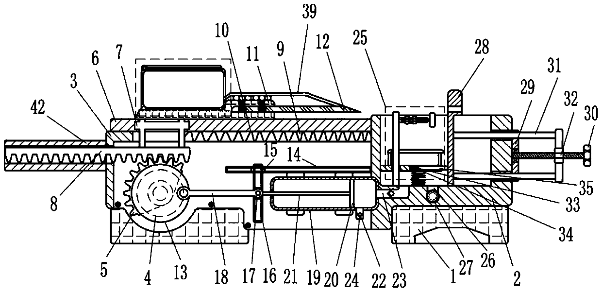
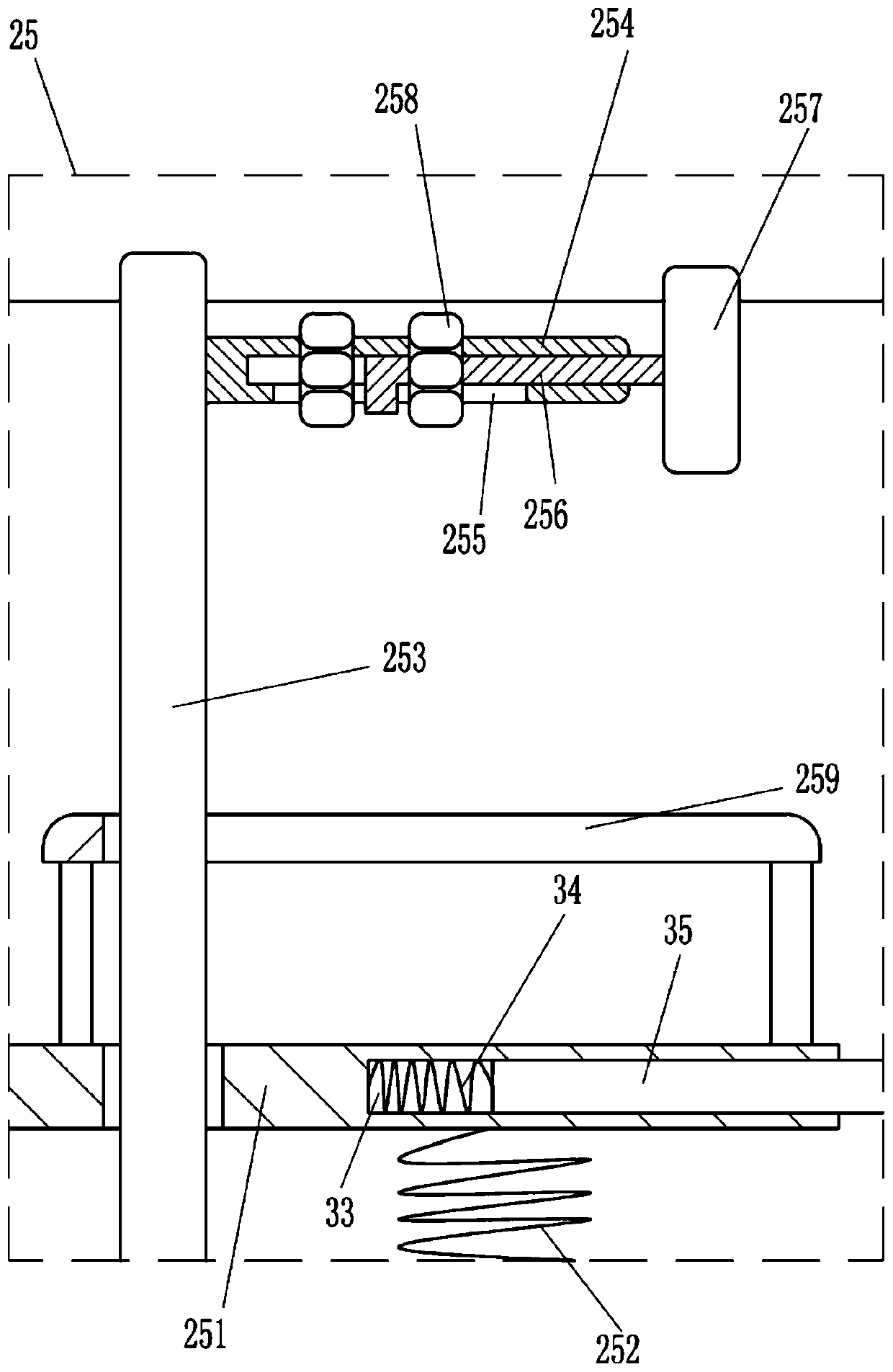
[0023] A ring-shaped NdFeB magnet slicer, see figure 1 and figure 2 , including a base 1, a placing frame 2, an L-shaped frame 3, a cutting device, a pushing device and a fixed lifting device 25, the right side of the top of the base 1 is fixed with a placing frame 2 with a groove inside, and the left side of the placing frame 2 An L-shaped frame 3 is installed on the side, and the bottom of the L-shaped frame 3 is fixed to the base 1 by bolts. A cutting device for horizontally slicing the ring-shaped NdFeB is installed on the L-shaped frame 3. A push ring is installed inside the L-shaped frame 3. The pushing device for the vertical movement of NdFeB, the fixed lifting device 25 for fixing the ring-shaped NdFeB is installed in the groove on the placement frame 2.
[0024] When cutting the ring-shaped NdFeB, first place the ring-shaped NdFeB to be cut on the fixed lifting device 25, and then fix the ring-shaped NdFeB. After the ring-shaped NdFeB is fixed, start the cutting de...
Embodiment 2
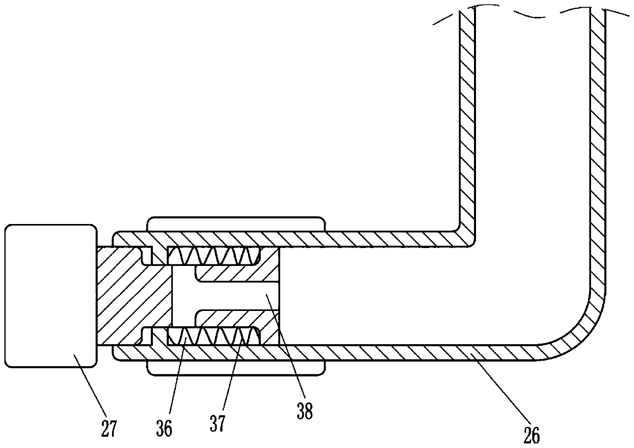
[0028] see figure 1 , the pushing device includes disc 13, first guide rail 14, first guide block 15, second guide rail 16, second guide block 17, rotating rod 18, cylinder body 19, first piston 20, pull rod 21, suction pipe 22, air intake pipe 23, one-way valve 24, air outlet pipe 26 and plug 27, are provided with disc 13 on the output shaft of reduction motor 4, and disc 13 is positioned at sector gear 5 front sides, and the left side of placement frame 2 is fixedly connected by bolts. The first guide rail 14, the first guide rail 14 is positioned in the L-shaped frame 3, the first guide block 15 that slides left and right is provided in the first guide rail 14, the first guide block 15 front side is provided with the second guide rail 16, the second guide rail 16 The second guide block 17 that slides up and down is provided inside, and the eccentric position of the front side of the disk 13 is rotated to be provided with a rotating rod 18, and the right end of the rotating ...
Embodiment 3
[0033] see figure 1 , in order to adjust the slice thickness of the ring-shaped NdFeB, it also includes a vertical plate 28, a backing plate 29, a solid threaded rod 30, a push rod 31, a second nut 32, a third spring 34 and a third piston 35, and the placement frame 2 The vertical plate 28 that slides left and right is provided in the groove on the top, the backing plate 29 is installed on the right side of the placement frame 2 by bolts, the middle part of the backing plate 29 is provided with a solid threaded rod 30 through the rotation of the bearing seat, and the right side of the vertical plate 28 has two upper and lower sides. Both sides are provided with a push rod 31, the right side of the push rod 31 passes through the right side of the placement frame 2 and the backing plate 29, the solid threaded rod 30 is equipped with a second nut 32, and the right part of the push rod 31 is connected with the second nut 32, The right part of the second piston 251 has a first groo...
PUM
 Abstract
Description
Claims
Application Information
 - R&D Engineer
- R&D Manager
- IP Professional
- Industry Leading Data Capabilities
- Powerful AI technology
- Patent DNA Extraction
Browse by: Latest US Patents, China's latest patents, Technical Efficacy Thesaurus, Application Domain, Technology Topic.
© 2024 PatSnap. All rights reserved.Legal|Privacy policy|Modern Slavery Act Transparency Statement|Sitemap