Roof structure and tile mounting assembly
A technology for installing components and roof structures, which can be applied to roofs, building structures, roof coverings, etc., and can solve the problems of laborious, complicated operation steps, and high labor intensity.
Pending Publication Date: 2019-09-27
汉瓦技术有限公司
0 Cites 0 Cited by
AI-Extracted Technical Summary
Problems solved by technology
Therefore, the installation method of the existing tiles has cumbersome operation steps, and the tiles need to be shaken repeatedly to make...
Method used
[0046] Through the tile installation assembly of the embodiment of the present invention, the tile 200 can be installed on an installation surface 100 inclined relative to the horizontal plane or a vertical installation surface 100, and the second side plate 12 can be abutted against it The second side arm 22 is supported, thereby supporting the tile 200. At the same time, the guide arm 24 can fit through the guide hole 111 to prevent the tile 200 from detaching from the first side arm 21 and stabil...
Abstract
The invention provides a roof structure and a tile mounting assembly, and relates to the technical field of solar energy. The tile mounting assembly is used for mounting tiles to a mounting surface. The tile mounting assembly includes a fixed beam and hooks. The fixed beam includes a first side plate and a second side plate. The first side plate and the second side plate are both fixed to the mounting surface, and the second side plate is arranged opposite to the first side plate. The first side plate is provided with a guiding hole. Each hook includes a first side arm, a second side arm and a guiding arm, the first side arm and the second side arm are both fixed on the tiles, the second side arm is arranged opposite to the first side arm, the guiding arm is disposed on the first side arm and penetrates through the guiding hole in a matching mode, and the second side arm abuts the surface, close to the first side plate, of the second side plate. According to the roof structure and the tile mounting assembly, installation efficiency can be improved, and labor intensity is reduced.
Application Domain
Roof covering using tiles/slates
Technology Topic
EngineeringFixed Beam +1
Image
Examples
- Experimental program(1)
Example Embodiment
[0039] Example embodiments will now be described more fully with reference to the accompanying drawings. However, the example embodiments can be implemented in various forms, and should not be construed as being limited to the embodiments set forth herein; on the contrary, these embodiments are provided so that the present invention will be comprehensive and complete, and fully convey the concept of the example embodiments To those skilled in the art. The same reference numerals in the figures represent the same or similar structures, and thus their detailed descriptions will be omitted.
[0040] Although relative terms such as "upper" and "lower" are used in this specification to describe the relative relationship between one component of an icon and another component, these terms are used in this specification only for convenience, for example, according to the drawings. The direction of the example described. It can be understood that if the device of the icon is turned over and turned upside down, the component described as "upper" will become the "lower" component. When a structure is “on” another structure, it may mean that a certain structure is integrally formed on another structure, or that a certain structure is “directly” arranged on another structure, or that a certain structure is “indirectly” arranged on another structure through another structure. On other structures.
[0041] The terms "a", "a", "the", "said" and "at least one" are used to indicate the presence of one or more elements/components/etc.; the terms "including" and "have" are used to indicate open-ended The inclusive means and means that in addition to the listed elements/components/etc. there may be other elements/components/etc.; the terms "first" and "second" etc. are only used as marks, not Limit the number of its objects.
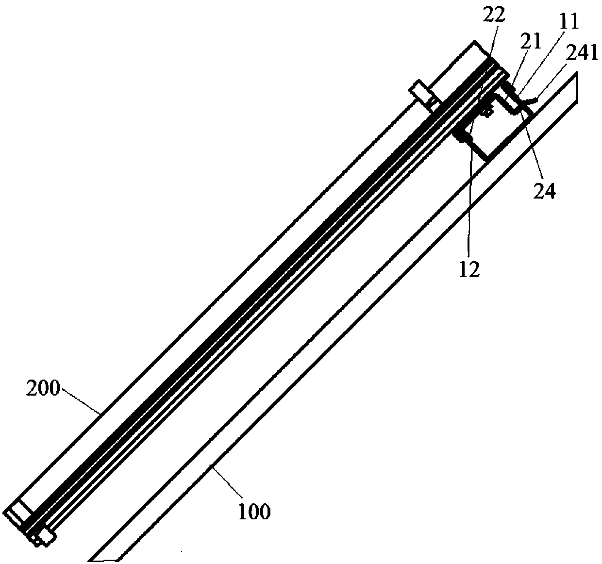
[0042] Such as figure 1 As shown, the embodiment of the present invention provides a tile mounting assembly for mounting tiles 200 on a mounting surface 100. The mounting surface 100 can be a flat surface inclined with respect to a horizontal plane, such as a sloped surface of a sloped roof. , It can also be other inclined planes or vertical planes. The tile 200 can be a solar tile such as a single-glass solar tile, a double-glass solar tile, or other types of tiles such as a waterproof tile and a heat insulation tile. It has a light-receiving surface and a backlight surface. The light-receiving surface is used to receive sunlight and backlight. The surface is used to connect with the installation surface 100. In the following, only the installation surface is a slope surface and the tile 200 is a solar tile as an example for description.
[0043] Such as Figure 1-Figure 4 As shown, the tile installation assembly of the embodiment of the present invention may include a fixed beam 1 and a hook 2, wherein:
[0044] The fixed beam 1 may include a first side plate 11 and a second side plate 12, the first side plate 11 and the second side plate 12 are both fixed on the mounting surface 100, and the second side plate 12 is arranged opposite to the first side plate 11, The first side plate 11 may be provided with a guide hole 111.
[0045] The hook 2 may include a first side arm 21, a second side arm 22 and a guide arm 24. The first side arm 21 and the second side arm 22 are both fixed on the tile 200. The second side arm 22 and the first side arm 21 In contrast, the guide arm 24 is disposed on the first side arm 21 and fits through the guide hole 111, and the second side arm 22 abuts against the surface of the second side plate 12 close to the first side plate 11.
[0046] With the tile mounting assembly of the embodiment of the present invention, the tile 200 can be mounted on a mounting surface 100 inclined with respect to a horizontal plane or a vertical mounting surface 100, and the second side plate 12 can abut against the second The side arms 22 support, thereby supporting the tile 200. At the same time, the guide arm 24 can fit through the guide hole 111, which can prevent the tile 200 from being separated from the first side arm 21 and stabilize the position of the tile 200. During installation, only need to lift the bottom of the tile 200, and make the guide arm 24 fit through the guide hole 111, and then rotate the tile 200 to drop the bottom of the tile 200, and then move the bottom of the tile 200 down It is sufficient to make the second side arm 22 abut on the second side plate 12 without reciprocating the tile 200, so that the efficiency of installation and disassembly can be improved, and the labor intensity can be reduced.
[0047] The components of the tile installation assembly of the embodiment of the present invention will be described in detail below:
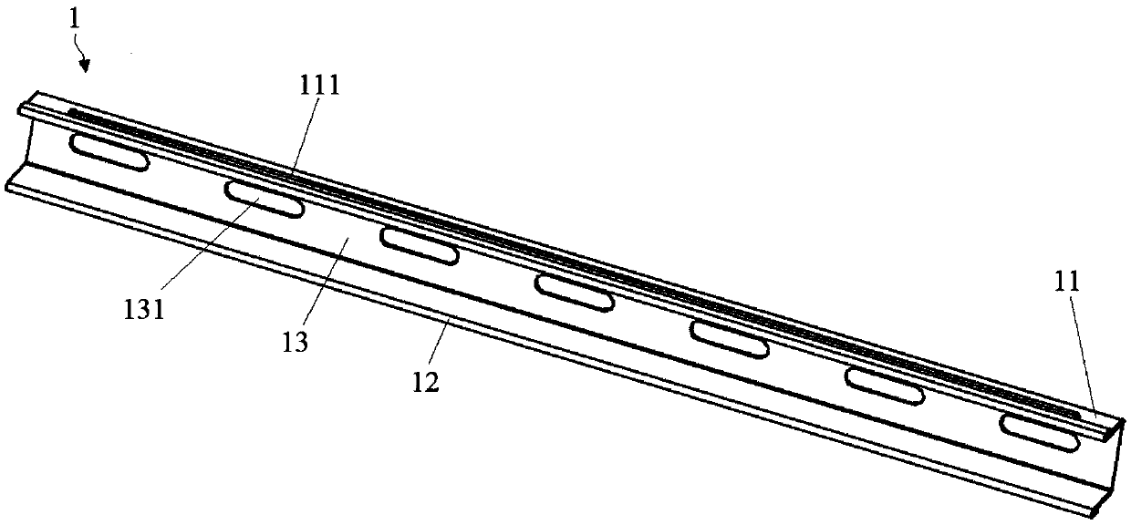
[0048] Such as figure 1 with figure 2 As shown, in one embodiment, the fixed beam 1 can be fixed on the mounting surface 100, and the fixed beam 1 can include a first side plate 11, a second side plate 12 and a fixed plate 13, wherein:
[0049] Such as figure 2 As shown, the fixing plate 13 may be a strip-shaped flat structure, and its shape may be a rectangular parallelepiped or the like. The fixing plate 13 can be provided with a mounting hole 131. During installation, the fixing plate 13 can be attached to the mounting surface 100, and a connector can be used to penetrate the mounting surface 100 through the mounting hole 131, thereby detachably fixing the fixing plate 13 to On the mounting surface 100, the connecting member can be threaded parts such as bolts or screws, but is not limited to this, and can also be riveted parts such as rivets. As long as the fixing plate 13 can be fixed to the mounting surface 100, it will not be described here. List one by one.
[0050] The shape of the mounting hole 131 may be a waist circle. In the embodiment where the connecting member is a screw member, when the screw member is loosened, the fixing plate 13 can be moved relative to the screw member to adjust the position of the fixing plate 13. Of course, the shape of the mounting hole 131 may also be a circle, an oval, or other shapes. The number of the mounting holes 131 can be multiple, such as five, six, seven, etc., and the multiple mounting holes 131 can be linearly distributed along the length direction of the fixing plate 13, and the number of the mounting holes 131 can be specifically determined by the fixing plate 13 Depending on the length, the longer the length of the fixing plate 13 is, the more the number of mounting holes 131 is.
[0051] In other embodiments of the present invention, the fixing plate 13 can also be fixed on the mounting surface 100 in other ways. For example, the fixing plate 13 can be fitted with a groove on the mounting surface 100 through a hook to fix the fixing plate 13 on the mounting surface 100. On face 100, I will not go into details here.
[0052] Such as figure 2 As shown, both the first side plate 11 and the second side plate 12 can have a flat plate structure, and the length can be the same as the length of the fixed plate 13. The first side plate 11 and the second side plate 12 can be connected to both sides of the fixed plate 13, so that the fixed beam 1 is a U-shaped beam, and when the installation surface 100 is a slope surface or a vertical surface, the fixed beam 1 is installed At this time, the second side plate 12 can be located below the first side plate 11. The connection between the first side plate 11 and the second side plate 12 and the fixing plate 13 may be welding, screw connection, etc., or integral molding.
[0053] Both the first side plate 11 and the second side plate 12 can be perpendicular to the fixing plate 13 and have the same height in the direction perpendicular to the fixing plate 13, that is, the side of the first side plate 11 away from the mounting surface 100 and the mounting surface 100 The distance of the second side plate 12 is the first distance, the distance between the side of the second side plate 12 away from the mounting surface 100 and the mounting surface 100 is the second distance, the first distance is the height of the first side plate 11, and the second distance is the second side The height of the board 12, the first distance may be the same as the second distance, so as to define that the tile 200 is parallel to the mounting surface 100. The distance between the first side plate 11 and the second side plate 12 may be greater than the distance between the first side arm 21 and the second side arm 22, so that the first side arm 21 and the second side arm 22 can be accommodated in the first side plate at the same time 11 and the space between the second side plate 12.
[0054] The first side plate 11 can be provided with a guide hole 111, the guide hole 111 is a through hole, and it can be strip-shaped, its width is greater than or equal to the thickness of the guide arm 24, and the guide hole 111 can simultaneously accommodate the guide hole A plurality of guide arms 24 are linearly distributed along the length direction of 111 so as to cooperate with the plurality of hooks 2. Of course, the shape and size of one guide hole 111 can also be matched with one guide arm 24, and the number of guide holes 111 can be multiple, and each guide hole 111 can be matched with multiple guide arms 24 in a one-to-one correspondence. Alternatively, one guide hole 111 can allow part of the guide arms 24 to pass through.
[0055] In other embodiments of the present invention, the fixed beam 1 may not include the fixing plate 13, but the first side plate 11 and the second side plate 12 can be directly fixed to the mounting surface 100, the first side plate 11 and the second side plate The structure of the plate 12 can refer to the first side plate 11 and the second side plate 12 of the above embodiment, which will not be described in detail here.
[0056] It should be noted that multiple fixed beams 1 can be fixed on the same mounting surface 100, and the multiple fixed beams 1 can be evenly distributed on the mounting surface 100 in multiple rows and multiple columns. The number of fixed beams 1 can be determined by the number of the mounting surface 100. It depends on the area and the number of tiles 200 required.
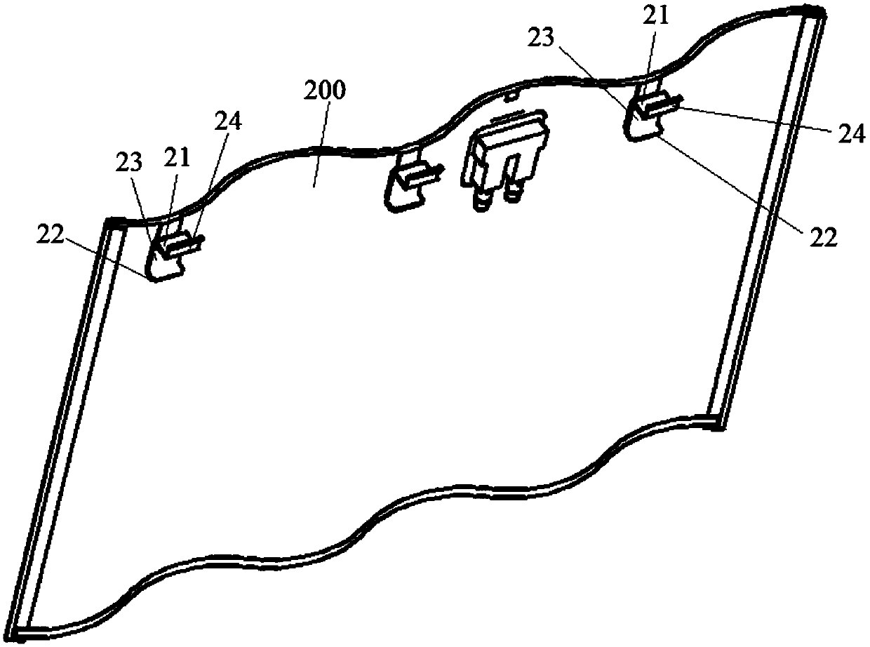
[0057] Such as image 3 with 4 As shown, in an embodiment, the hook 2 may include a first side arm 21, a second side arm 22, a bottom plate 23 and a guide arm 24, wherein:
[0058] Such as image 3 As shown, the bottom plate 23 can be a flat plate structure, and its shape can be a rectangular parallelepiped, a cube, or the like. The bottom plate 23 can be attached to the backlight surface of the tile 200, and can be fixed by a screw member such as bolts or screws, so that the bottom plate 23 can be detachably fixed to the backlight surface of the tile 200. Of course, the bottom plate 23 can also be fixed to the backlight surface in other ways.
[0059] Such as Figure 4 As shown, both the first side arm 21 and the second side arm 22 may have a flat structure. The first side arm 21 and the second side arm 22 can be connected to both sides of the bottom plate 23 so that the hook 2 has a U-shaped structure. The connection between the first side arm 21 and the second side arm 22 and the bottom plate 23 may be welding, screw connection or the like, or it may be integrally formed. Both the first side arm 21 and the second side arm 22 can be perpendicular to the bottom plate 23, and the distance between the first side arm 21 and the second side arm 22 can be smaller than the distance between the first side plate 11 and the second side plate 12, so that the The side arm 21 and the second side arm 22 can be simultaneously accommodated in the space between the first side plate 11 and the second side plate 12, and the second side arm 22 abuts the second side arm 22 close to the first side arm 21 On the surface, there is a gap between the first side arm 21 and the first side plate 11 so that the hook 2 can move between the first side plate 11 and the second side plate 12.
[0060] Such as Figure 4 As shown, the guide arm 24 can be provided at the end of the first side arm 21 away from the bottom plate 23, that is, the end away from the tile 200, and it can be integrally formed by bending the first side arm 21 outward, that is, away from the second side. The direction of the arm 22 is bent. The angle between the guide arm 24 and the first side arm 21 can be 90° to 120°, such as 90°, 100°, or 120°, so that the guide arm 24 can fit through the guide hole 111, so that the guide arm 24 and The cooperation of the guide hole 111 limits the position of the hook 2. The guide arm 24 can rotate with the first side arm 21 and pass through the guide hole 111. Of course, the guide arm 24 can also be a plate-shaped structure independent of the first side arm 21, and it can be connected to the first side arm 21 by welding or the like. It should be noted that the angle between the guide arm 24 and the first side arm 21 may be determined according to the size of the guide hole 111, as long as the guide arm 24 can pass through the guide hole 111.
[0061] In addition, the end of the guide arm 24 away from the first side arm 21 is bent toward the tile 200 to form a bent portion 241. When the guide arm 24 is moved toward the guide hole 111, it can play a guiding role and prevent the guide arm from moving. 24 escapes from the guide hole 111 at will. Of course, the bending part 241 may not be provided.
[0062] In another embodiment of the present invention, the structure of the fixed beam 1 may be the same as the above-mentioned embodiment, and the distance between the first side arm 21 and the second side arm 22 may be greater than the distance between the first side plate 11 and the second side plate 12 During installation, the second side arm 22 can be located between the first side plate 11 and the second side plate 12, and the second side arm 22 abuts against the second side plate 12, and the first side arm 21 is located on the first side The outer side of the board 11, that is, the side away from the second side board 12. The guide arm 24 can be bent toward the second side arm 22 and can pass through the guide hole 111 and can also fix the tile 200 to the mounting surface 100.
[0063] It should be noted that the number of hooks 2 can be multiple, and the plurality of hooks 2 are distributed in a straight line. The guide arm 24 of each hook 2 can fit through the same guide hole 111, and the second side arm 22 of each hook 2 can abut On the second side plate 12 of the fixed beam 1.
[0064] The following describes the installation process of the tile installation assembly of the embodiment of the present invention:
[0065] The fixing beam 1 can be fixed to the mounting surface 100 by screws, and the hook 2 can be fixed to the backlight surface of the tile 200. Then, the bottom of the tile 200 can be lifted, and the first side arm 21 of the hook 2 can be inserted between the first side plate 11 and the second side plate 12 of the fixed beam 1, and the first side plate 11 can be pressed against To the point where the first side arm 21 and the tile 200 meet; then, rotate the tile 200 with the edge of the first side plate 11 as an axis, so that the bottom of the tile 200 falls, and the guide arm 24 passes through the guide hole 111, The second side arm 22 moves between the first side plate 11 and the second side plate 12. Finally, the tile 200 can be moved down so that the second side arm 22 abuts against the second side plate 12, and the tile 200 can be fixed on the fixed beam 1 under the action of the weight of the tile 200. During this process, the guide arm 24 of the hook 2 can play a guiding role. When the installer cannot see the backlight surface of the tile 200, the tile 200 can also be installed in place without reciprocating the tile, so that the efficiency of installation and disassembly can be improved, and the labor intensity can be reduced.
[0066] Such as figure 1 As shown, the embodiment of the present invention also provides a roof structure. The roof structure of this embodiment may include a roof, tiles 200 and the tile installation assembly of any of the above embodiments, wherein:
[0067] The roof may be a sloping roof, and the roof may have an installation surface 100 inclined relative to the horizontal plane, and the shape, size, and number of the installation surface 100 are not specifically limited. The mounting surface 100 may be a flat structure, or a frame structure formed by staggered beams.
[0068] The tile 200 may be a solar tile, the shape and size of which are not specifically limited herein, and may include a substrate, a back electrode, an absorption layer, etc., which are not described in detail here. Each mounting surface 100 can be provided with multiple tiles 200, and each tile 200 can be detachably installed on the mounting surface 100 through a tile mounting assembly to generate electricity. The specific composition of the tile mounting assembly can be referred to The tile installation assembly in any of the above embodiments will not be described in detail here. In other embodiments of the present invention, the tiles 200 may also be other types of tiles such as waterproof tiles and heat insulation tiles, which will not be described in detail here.
[0069] For the beneficial effects of the roof structure of the embodiment of the present invention, reference may be made to the beneficial effects of the above-mentioned tile installation assembly, which will not be repeated here.
[0070] Such as Figure 5 As shown, the embodiment of the present invention also provides a method for using the tile installation assembly, which is used for the above-mentioned tile installation assembly, and the use method may include step S110 to step S130.
[0071] In step S110, the tile 200 is pressed against the first side plate 11, and the guide arm 24 is matched with the guide hole 111. Such as Image 6 As shown, Image 6 The tile installation assembly after completing step S110 is shown.
[0072] In step S120, with the edge of the first side plate 11 in contact with the tile 200 as an axis, the tile 200 is rotated so that the guide arm 24 passes through the guide hole 111, and the second side arm 22 is located between the first side plate 11 and Between the second side plates 12. Such as Figure 7 As shown, Figure 7 The tile installation assembly after completing step S120 is shown.
[0073] In step S130, the tile 200 is moved so that the second side arm 22 abuts against the second side plate 12. Such as figure 1 As shown, figure 1 The tile installation component after the completion of step S130 is shown, that is, the tile installation component after the installation is completed.
[0074] After considering the specification and practicing the invention disclosed herein, those skilled in the art will easily think of other embodiments of the present invention. This application is intended to cover any variations, uses, or adaptive changes of the present invention. These variations, uses, or adaptive changes follow the general principles of the present invention and include common knowledge or conventional technical means in the technical field not disclosed by the present invention. . The description and the embodiments are only regarded as exemplary, and the true scope and spirit of the present invention are pointed out by the appended claims.
PUM
Property | Measurement | Unit |
Angle | 90.0 ~ 120.0 | deg |
Description & Claims & Application Information
We can also present the details of the Description, Claims and Application information to help users get a comprehensive understanding of the technical details of the patent, such as background art, summary of invention, brief description of drawings, description of embodiments, and other original content. On the other hand, users can also determine the specific scope of protection of the technology through the list of claims; as well as understand the changes in the life cycle of the technology with the presentation of the patent timeline. Login to view more.