Auxiliary device for installation and positioning of claw poles

A technology for installation, positioning and auxiliary devices, which is applied in the direction of electromechanical devices, workpiece clamping devices, manufacturing stator/rotor bodies, etc., can solve problems such as difficult to ensure assembly accuracy, and achieve good stability, not easy to shake, and convenient adjustment.

Pending Publication Date: 2019-10-01
武汉欣力瑞机电设备有限公司
View PDF0 Cites 5 Cited by
  • Summary
  • Abstract
  • Description
  • Claims
  • Application Information

AI Technical Summary

Problems solved by technology

[0002] During the installation process of the generator rotor, the field winding and the yoke are installed on the generator shaft and then two opposite claw poles are installed. When the claw poles are installed on the claw pole insta

Method used


Image

  • Auxiliary device for installation and positioning of claw poles
  • Auxiliary device for installation and positioning of claw poles
  • Auxiliary device for installation and positioning of claw poles

Examples


Embodiment 1

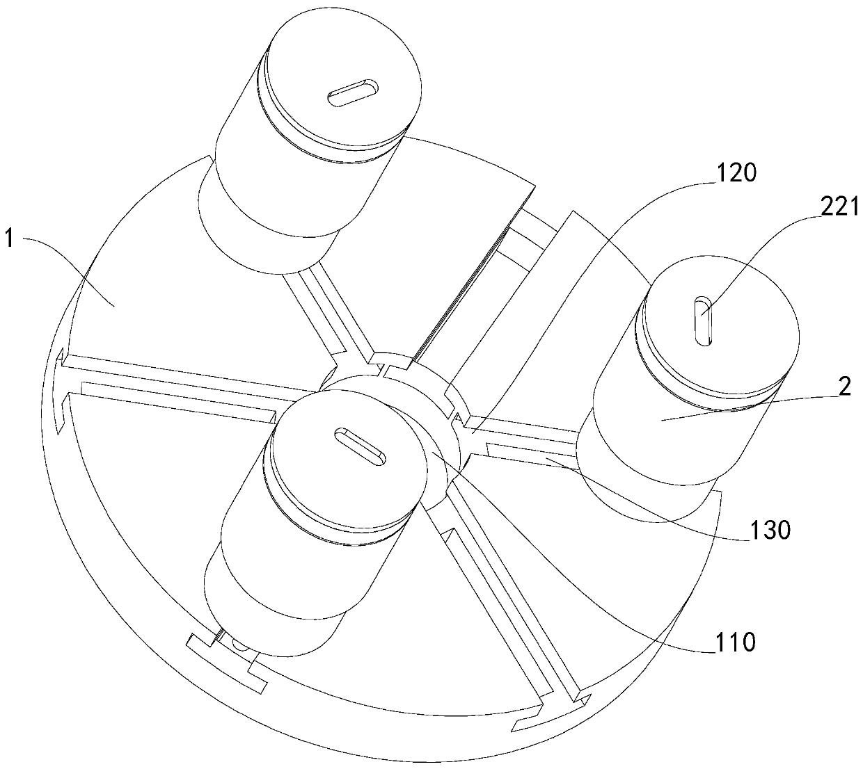
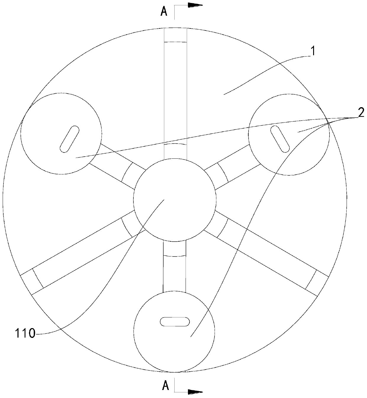
[0029] Such as figure 1 , figure 2 , image 3 As shown, a claw pole installation and positioning auxiliary device includes a base 1 and a positioning assembly 2, the base 1 is provided with a socket 110, and a plurality of positioning assemblies 2 are arranged on the circumference with the socket 110 as the center of the circle, and multiple positioning The angular distribution of the assembly 2 matches the angular distribution of the ratchets of the claw poles to be installed. The socket 110 is mainly used to allow the shaft 3 of the two claw poles to be installed to pass through. The inner diameter of the socket 110 is preferably equal to the outer diameter of the rotary shaft 3 The number of positioning components 2 is determined according to the number of pawls to be installed with claw poles. For example, when a claw pole containing six pawls needs to be positioned, the number of positioning components 2 can be three or six, as Taking three as an example, at this time,...

Embodiment 2

[0032] This embodiment is a further improvement made on the basis of Embodiment 1, specifically as follows:

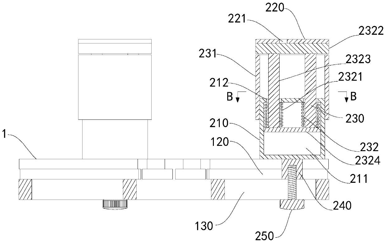
[0033] In the embodiment, the positioning assembly 2 also includes a linear lifting mechanism 230, the linear lifting mechanism 230 is arranged on the positioning column 210, the positioning plate 220 is arranged on the linear lifting mechanism 230, and the linear lifting mechanism 230 can drive the positioning plate 220 to move up and down. Move, thereby changing the distance between the positioning plate 220 and the positioning column 210, so that the claw pole installation and positioning auxiliary device can meet the assembly of various claw poles with different heights.

[0034] The linear lifting mechanism 230 includes a positioning sleeve 231 and a rotation stopper 232. The inner wall surface of the positioning sleeve 231 is provided with internal threads, and the outer circumferential surface of the positioning column 210 is provided with external threads. The p...


PUM


Abstract

The invention relates to an auxiliary device for installation and positioning of claw poles. The auxiliary device comprises a base and a plurality of positioning assemblies, wherein an insertion holeis formed in the base, the plurality of positioning assemblies are arranged on the circumference with the insertion hole as a circle center, the positioning assemblies comprise positioning columns andpositioning plates, the positioning columns are arranged on the base, the positioning plates are arranged on the positioning columns, and positioning grooves matched with the tips of pawls of the claw poles are formed in the positioning plates. The auxiliary device has the beneficial effects that during use, a rotating shaft penetrates through the insertion hole, and then one claw pole is sleevedon the rotating shaft, the pawls are ensured to face upwards, the positioning columns are clamped among the pawls of the claw pole so as to enable the claw pole to be positioned in the circumferential direction, a magnetic field winding and a magnetic yoke are arranged on the rotating shaft, and finally the other claw pole is arranged on the rotating shaft, the pawls of the other claw pole facesdownwards, the tips of the pawls are clamped into the positioning grooves so as to enable the other claw pole to be positioned in the circumferential direction and not easy to shake; and in this way,the integral assembly accuracy is easy to guarantee during manual assembly.

Description

technical field [0001] The invention relates to an auxiliary device for installing and positioning claw poles. Background technique [0002] During the installation process of the generator rotor, the field winding and the yoke are installed on the generator shaft and then two opposite claw poles are installed. When the claw poles are installed on the claw pole installation place of the shaft, the claw poles are partially squeezed and compacted. The yoke is fixed, and the existing assembly is generally done manually, and it is difficult to guarantee the overall assembly accuracy by manual assembly. Contents of the invention [0003] The technical problem to be solved by the present invention is to provide an auxiliary device for installing and positioning claw poles, so as to overcome the above-mentioned deficiencies in the prior art. [0004] The technical solution of the present invention to solve the above technical problems is as follows: a claw pole installation and ...

Claims


Application Information

Patent Timeline
IPC IPC(8): B25B11/00H02K15/00H02K15/02
CPCB25B11/00H02K15/00H02K15/02H02K15/022
Inventor 不公告发明人
Owner 武汉欣力瑞机电设备有限公司
Why Eureka
Try Eureka