Installation structure and installation method of car door machine, main connecting bracket and auxiliary connecting bracket

A technology of installation structure and door machine, which is applied in the direction of transportation and packaging, elevators in buildings, etc., to achieve the effect of saving installation costs, simple and reasonable installation process, and improving firmness

Active Publication Date: 2022-04-12
SHANGHAI MITSUBISHI ELEVATOR CO LTD
View PDF7 Cites 0 Cited by
  • Summary
  • Abstract
  • Description
  • Claims
  • Application Information

AI Technical Summary

Problems solved by technology

[0003] The technical problem to be solved by the present invention is to save materials for the installation of the car door operator, improve the firmness and stability of the door operator installed on the car, make the installation process simple and reasonable, and save installation cost

Method used


Image

  • Installation structure and installation method of car door machine, main connecting bracket and auxiliary connecting bracket
  • Installation structure and installation method of car door machine, main connecting bracket and auxiliary connecting bracket
  • Installation structure and installation method of car door machine, main connecting bracket and auxiliary connecting bracket

Examples


Embodiment 1

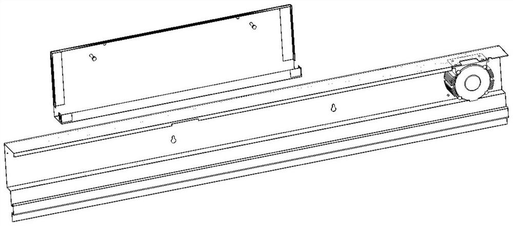
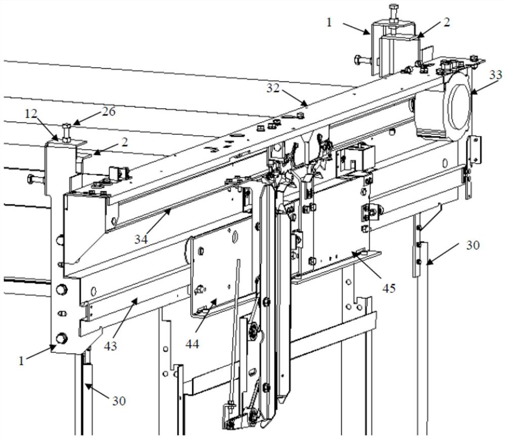
[0093] Such as image 3 , Figure 4 , Figure 5 As shown, the car door machine includes a door machine beam 32, and the installation structure of the car door machine includes a main connecting bracket 1 and an auxiliary connecting bracket 2;

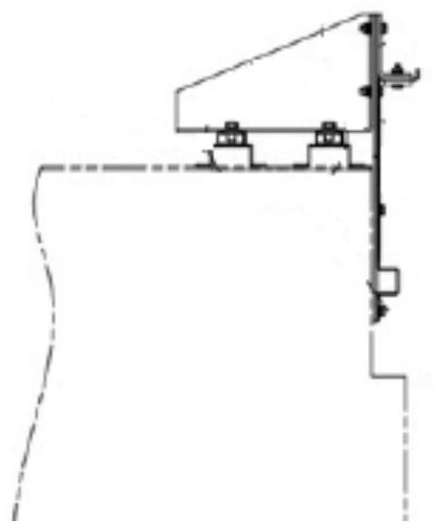
[0094] The main connecting bracket 1 is used to be fixed on the back of the door machine crossbeam 32 through bolt connection;

[0095] The auxiliary connecting bracket 2 is used to install and fix the corner of the elevator car through bolts;

[0096] The main connecting bracket 1 and the auxiliary connecting bracket 2 are connected and fixed by bolts, and the car door operator is installed on the car.

[0097] Preferably, the auxiliary connecting bracket 2 is used to install and fix the side wall or the front wall of the car at the corner of the elevator car through bolts.

[0098] Preferably, the installation point of the auxiliary connecting bracket 2 at the corner of the elevator car is not lower than the level where the door o...

Embodiment 2

[0101] Based on the installation structure of the car door machine of embodiment one, such as Figure 6 , Figure 7 , Figure 8 , Figure 9 As shown, the main connecting bracket 1 includes a first main vertical installation surface 14, a second main vertical installation surface 15, a main horizontal support surface 16, a main vertical engaging surface 17, a main vertical connection surface 11, a main Horizontal adjustment surface 12, main vertical adjustment surface 13;

[0102] The first main vertical installation surface 14 and the second main vertical installation surface 15 are respectively vertically connected to the outer front end of the main vertical connection surface 11;

[0103] The first main vertical installation surface 14 is above the second main vertical installation surface 15;

[0104] The front end of the main vertical connecting surface 11 protrudes forward under the second main vertical mounting surface 15 and is bent upward to form a main horizontal ...

Embodiment 3

[0131] Based on the installation structure of the car door machine of embodiment one, such as image 3 , Figure 4 , Figure 5 As shown, the installation structure of the car door machine includes two main connecting brackets 1 and two auxiliary connecting brackets 2;

[0132] The structure of the two main connecting brackets 1 is reversely symmetrical, and they are installed symmetrically around the center of the beam of the portal machine;

[0133] The structures of the two auxiliary connecting brackets 2 are reversely symmetrical, and are symmetrically installed at two corners of the elevator car with the center of the car as the center.

[0134] A waist-shaped hole in the vertical direction is reserved at the upper part of the beam guide rail of the door machine; the door guide rail 43 of the car door machine is an S-shaped bending guide rail, which can be 50mm or 115mm away from the bottom surface of the guide rail in the vertical direction on the upper side of the S-sh...


PUM


Abstract

The invention discloses an installation structure of a car door machine, which comprises a main connecting bracket and an auxiliary connecting bracket; the main connecting bracket is used to be connected and fixed on the back of the beam of the door machine by bolts; the auxiliary connecting bracket is used to be installed and fixed on the elevator by bolts The corner of the car; the connecting bracket and the auxiliary connecting bracket are connected and fixed by bolts, and the car door operator is installed on the car. The invention also discloses the installation method of the car door machine adopting the installation structure, the main connection bracket and the auxiliary connection bracket. The invention can save materials for the installation of the door operator of the car, improve the firmness and stability of the door operator installed on the car, the installation process is simple and reasonable, and the installation cost is saved.

Description

technical field [0001] The invention relates to an elevator device, in particular to an installation structure and an installation method of a car door machine, a main connecting bracket and an auxiliary connecting bracket. Background technique [0002] The current installation structure of the car door operator, when the door operator is installed on the car, such as figure 1 As shown in the figure, the way of installing on the upper plate at the entrance or on the car roof is generally adopted. When installed on the upper plate of the entrance or the front wall, since the upper plate of the entrance and exit is generally relatively thin, if the weight of the door machine itself or the hanging car door is heavy, it is easy to cause deformation of the installation bracket and the upper plate of the entrance and exit, affecting the door. machine running. When the door operator is installed on the car top, if figure 2 As shown, the weight of the door machine and the car do...

Claims


Application Information

Patent Timeline
Patent Type & Authority Patents(China)
IPC IPC(8): B66B13/30B66B13/00
CPCB66B13/30B66B13/00
Inventor 张艺潘鹏胜童正国
Owner SHANGHAI MITSUBISHI ELEVATOR CO LTD
Why Eureka
Try Eureka