Insert and pull connection structure, supporting leg and frame connection assembly and crane
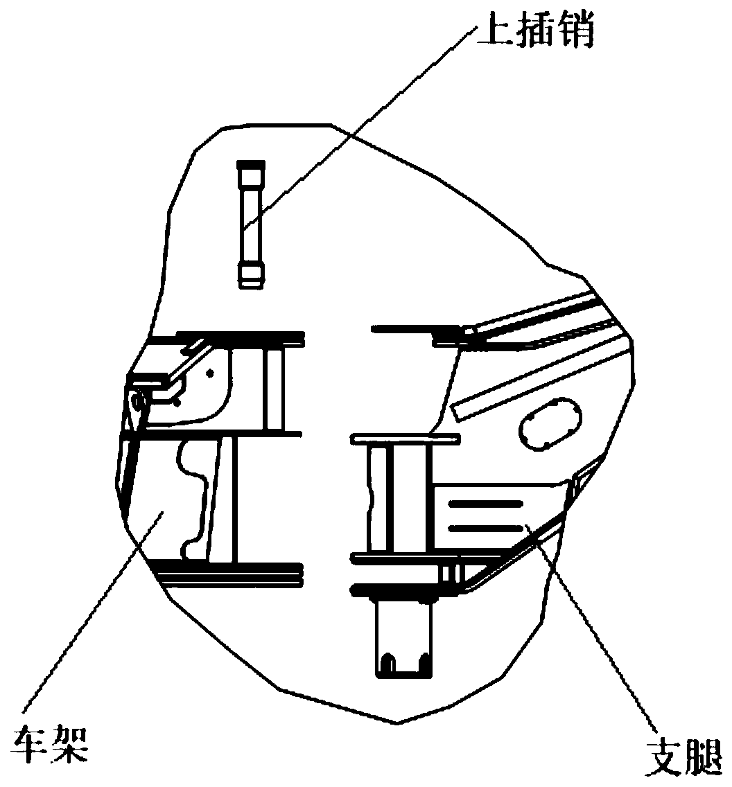
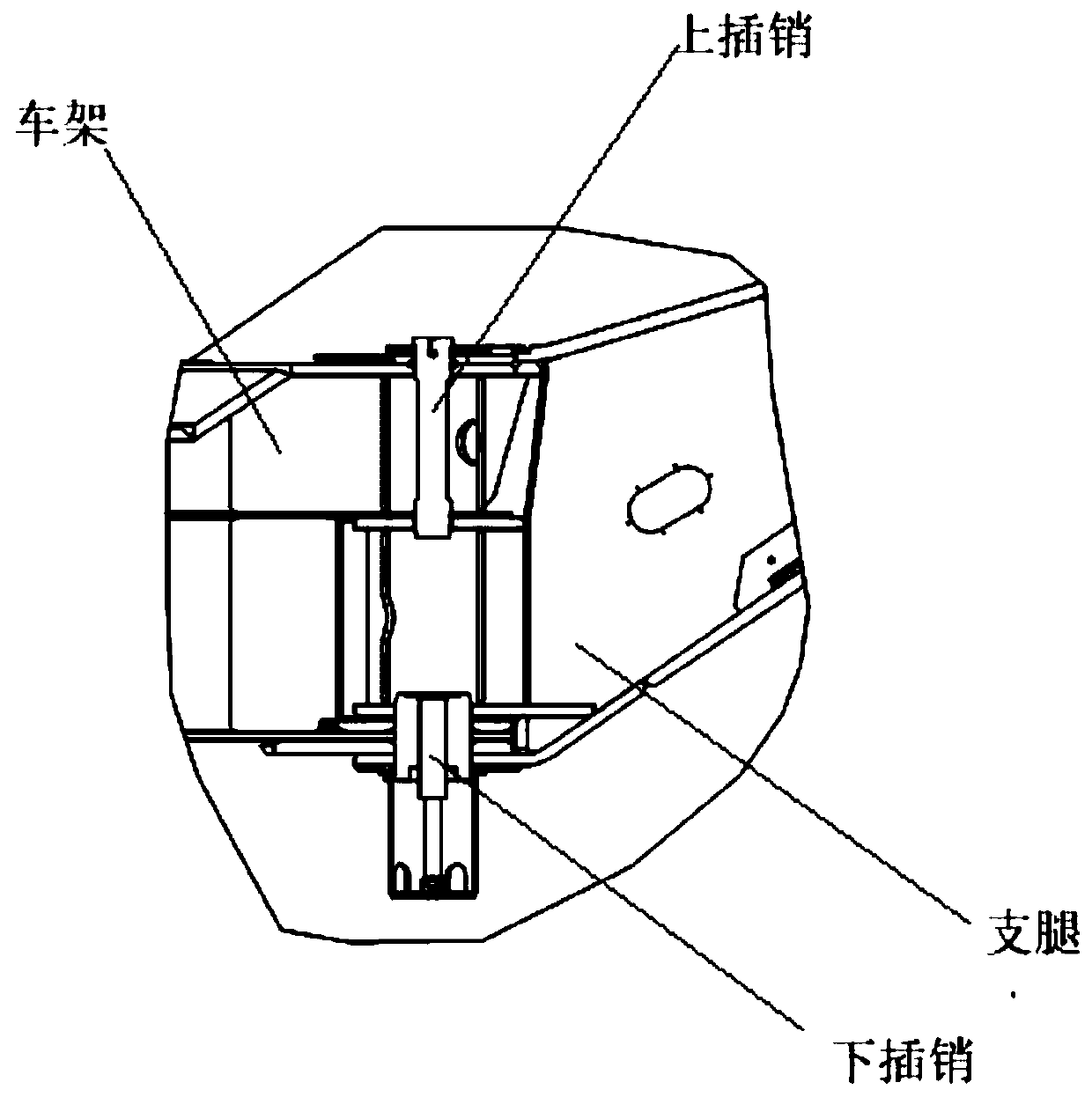
A technology of plug-in connection and connection components, which is applied in the direction of cranes, etc., can solve the problems of time-consuming and labor-intensive installation and disassembly of the connection and disassembly of the oil cylinder and the frame, and the difficulty of installing the upper and lower bolts, so as to improve the installation efficiency and save manpower. Effect
- Summary
- Abstract
- Description
- Claims
- Application Information
AI Technical Summary
Problems solved by technology
Method used
Image
Examples
Embodiment 1
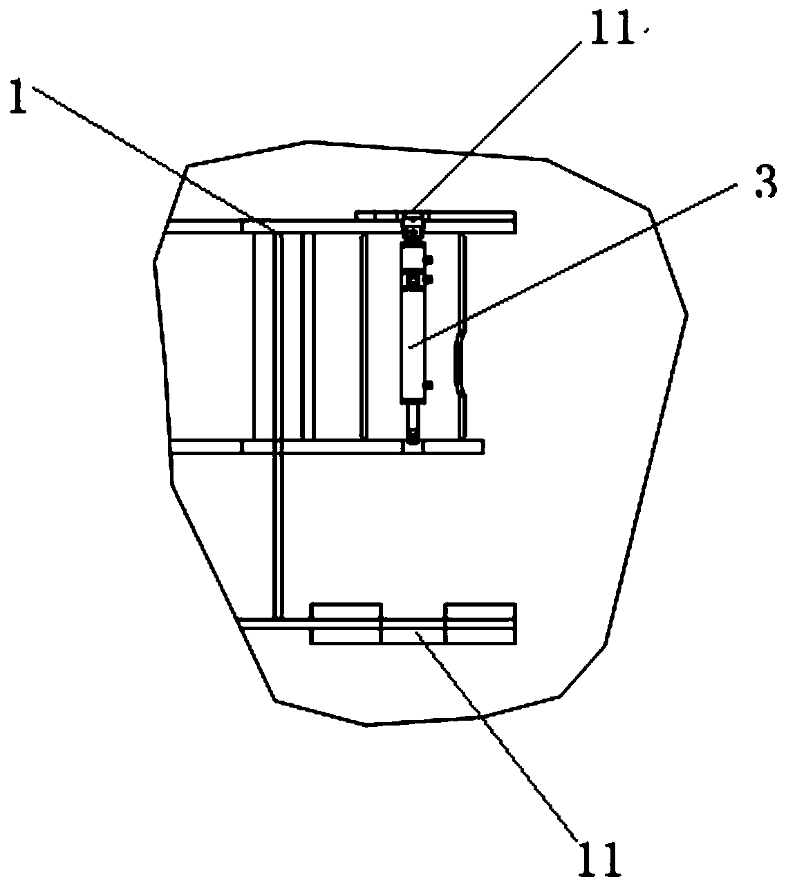
[0049] image 3It is a schematic structural diagram of the frame of the lifting equipment provided by the embodiment of the present invention in a perspective, Figure 4 A schematic view of the structure of the outriggers of the lifting equipment provided by the embodiment of the present invention in a perspective, Figure 5 A schematic structural diagram of the plug-in connection structure provided by the embodiment of the present invention in a perspective, and Fig. 6 is a schematic diagram provided by the embodiment of the present invention Figure 5 exploded view of ; see Figure 3-6 As shown, this embodiment provides a plug-in connection structure, which is used to connect the vehicle frame 1 to the outrigger 2.
[0050] The plug-in connection structure includes a two-way oil cylinder 3, an upper bolt 4 and a lower bolt 5, and the first end of the two-way oil cylinder 3 is used to drive the upper bolt 4, so that the upper part of the vehicle frame 1 is connected to the ...
Embodiment 2
[0058] see Figure 3-8 As shown, this embodiment provides a connection assembly between the outrigger and the frame, and this embodiment includes the frame, the outrigger and the plug-in connection structure described in Embodiment 1;
[0059] Wherein, the upper and lower positions of the vehicle frame 1 are provided with frame shaft holes 11, and the upper and lower positions of the legs 2 are provided with leg shaft holes 21 coaxial with the frame shaft holes 11; The upper pin 4 is used to pass through the upper position of the leg shaft hole 21 and the frame shaft hole 11 so that the frame 1 is connected to the upper part of the leg 2; the lower pin 5 It is used to pass through the leg shaft hole 21 at the lower position and the frame shaft 11 hole so that the frame 1 is connected to the lower part of the leg 2 .
[0060] Figure 9 For a schematic view of the structure of the rotary pallet provided by the embodiment of the present invention at a viewing angle, please refe...
Embodiment 3
[0067] This embodiment provides a crane, which includes the outrigger and frame connection assembly described in Embodiment 2.
[0068] For example, the crane in this embodiment includes a vehicle frame, outriggers and a plug-in connection mechanism. The plug-in connection structure includes a two-way oil cylinder, an upper bolt and a lower bolt, and the first end of the two-way oil cylinder is used to drive the upper bolt. , so that the upper part of the frame is connected to the upper part of the leg through the upper pin, and the second end of the two-way oil cylinder is used to drive the lower pin, so that the lower part of the frame is connected to the The lower part of the leg is connected by the lower pin;
[0069] The two-way oil cylinder is installed on the frame, and the upper and lower positions of the frame are provided with frame shaft holes, and the upper and lower positions of the legs are provided with legs coaxial with the frame shaft holes. shaft hole; the u...
PUM
 Abstract
Description
Claims
Application Information
 - R&D
- Intellectual Property
- Life Sciences
- Materials
- Tech Scout
- Unparalleled Data Quality
- Higher Quality Content
- 60% Fewer Hallucinations
Browse by: Latest US Patents, China's latest patents, Technical Efficacy Thesaurus, Application Domain, Technology Topic, Popular Technical Reports.
© 2025 PatSnap. All rights reserved.Legal|Privacy policy|Modern Slavery Act Transparency Statement|Sitemap|About US| Contact US: help@patsnap.com


