Video tag adjusting method, system and equipment
A technology of video labeling and adjustment method, which is applied in closed-circuit television systems, image data processing, instruments, etc., can solve the problems of camera rotation, inefficient restoration of original coordinates, inability of label positions and actual positions, etc., to achieve the effect of easy operation.
- Summary
- Abstract
- Description
- Claims
- Application Information
AI Technical Summary
Problems solved by technology
Method used
Image
Examples
Embodiment 1
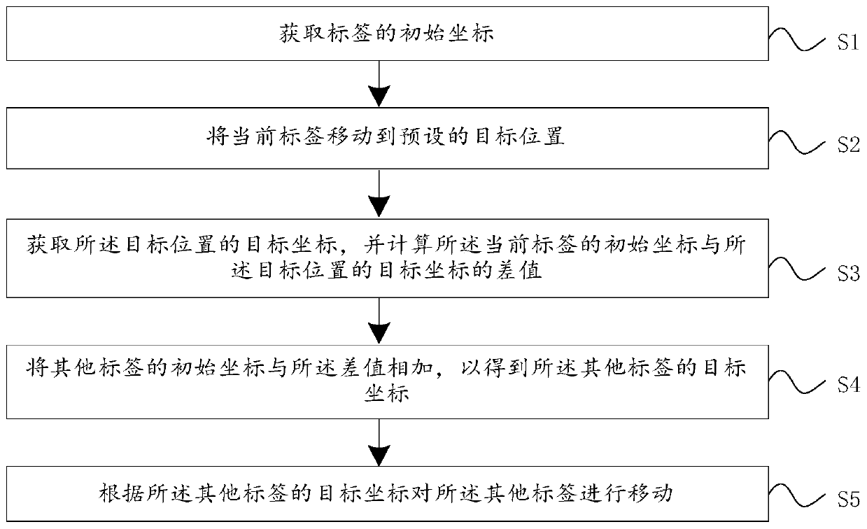
[0040] see figure 1 , figure 1 It is a flowchart of a video adjustment method provided by an embodiment of the present invention; including:
[0041] S1. Obtain the initial coordinates of the label;
[0042] S2. Move the current label to a preset target position;
[0043] S3. Obtain the target coordinates of the target position, and calculate the difference between the initial coordinates of the current tag and the target coordinates of the target position;
[0044] S4. Add the initial coordinates of other tags to the difference to obtain the target coordinates of the other tags;
[0045] S5. Moving the other tags according to the target coordinates of the other tags.
[0046] It is worth noting that the video adjustment method described in the embodiment of the present invention can be implemented by a client, the client includes a display screen, the client communicates with the camera, and is used to obtain the video captured by the camera, and convert the video to dis...
Embodiment 2
[0060] see Figure 7 , Figure 7 It is a schematic structural diagram of a video tag adjustment system 10 provided by an embodiment of the present invention; it includes:
[0061] The coordinate acquisition module 11 is used to acquire the initial coordinates of the label; it is also used to acquire the target coordinates of the preset target position;
[0062] The calculation module 12 is used to calculate the difference between the initial coordinates of the current label and the target coordinates of the target position; it is also used to add the initial coordinates of other labels to the difference to obtain the target coordinates of the other labels ;
[0063] The moving module 13 is configured to move the current tag to the target position; and is also configured to move the other tags according to the target coordinates of the other tags.
[0064] It is worth noting that the video tag adjustment system 10 described in the embodiment of the present invention may be a...
Embodiment 3
[0075] see Figure 8 , Figure 8 It is a schematic structural diagram of a video tag adjustment device 20 provided by an embodiment of the present invention; the video tag adjustment device 20 of this embodiment includes: a processor 21, a memory 22, and stored in the memory 22 and can be used in the processor 21 computer program running on it. When the processor 21 executes the computer program, the steps in the embodiment of the above-mentioned video adjustment method are implemented, for example figure 1 Steps S1-S5 are shown. Alternatively, when the processor 21 executes the computer program, it realizes the functions of each module / unit in the above-mentioned device embodiments, for example, the coordinate acquisition module 11 .
[0076] Exemplarily, the computer program can be divided into one or more modules / units, and the one or more modules / units are stored in the memory 22 and executed by the processor 21 to complete this invention. The one or more modules / unit...
PUM
 Abstract
Description
Claims
Application Information
 - R&D
- Intellectual Property
- Life Sciences
- Materials
- Tech Scout
- Unparalleled Data Quality
- Higher Quality Content
- 60% Fewer Hallucinations
Browse by: Latest US Patents, China's latest patents, Technical Efficacy Thesaurus, Application Domain, Technology Topic, Popular Technical Reports.
© 2025 PatSnap. All rights reserved.Legal|Privacy policy|Modern Slavery Act Transparency Statement|Sitemap|About US| Contact US: help@patsnap.com


