
Light sensation driving circuit, driving method thereof and display device

A driving circuit and light-sensing technology, which is applied in static indicators, printing image acquisition, instruments, etc., can solve the problems of fingerprint identification, large parasitic capacitance, and different signals, etc., and achieve the effect of improving the effect of fingerprint identification

Active Publication Date: 2019-10-01
WUHAN TIANMA MICRO ELECTRONICS CO LTD
View PDF7 Cites 6 Cited by
  • Summary
  • Abstract
  • Description
  • Claims
  • Application Information

AI Technical Summary

Problems solved by technology

However, this method requires an external fingerprint identification chip, which is complex in process, high in cost, and cannot realize full-screen fingerprint identification.
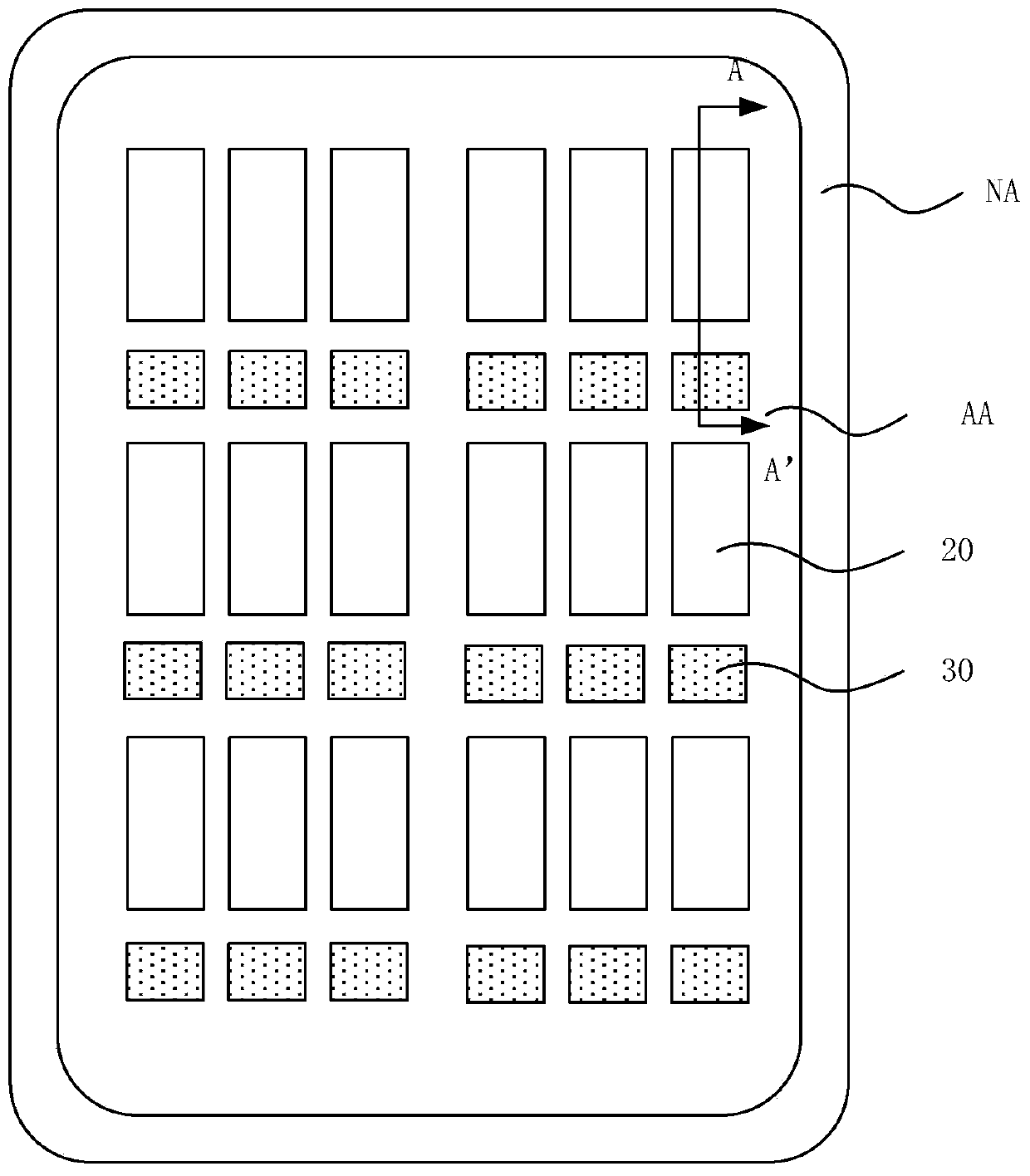
However, in the prior art research on integrated fingerprint recognition in the screen, it was found that due to the layout design of the organic light-emitting (OLED) display panel, the parasitic capacitance on the reading line is very large, and the parasitic capacitance on each line is not the same, which leads to The light-sensing signals generated by the same intensity of light are different from the signals read by different reading lines, resulting in the inability to accurately complete fingerprint identification

Method used


Image

  • Light sensation driving circuit, driving method thereof and display device
  • Light sensation driving circuit, driving method thereof and display device
  • Light sensation driving circuit, driving method thereof and display device

Examples


Embodiment Construction

[0021] In order to better understand the technical solutions of the present invention, the embodiments of the present invention will be described in detail below in conjunction with the accompanying drawings.

[0022] It should be clear that the described embodiments are only some of the embodiments of the present invention, not all of them. Based on the embodiments of the present invention, all other embodiments obtained by persons of ordinary skill in the art without creative efforts fall within the protection scope of the present invention.

[0023] Terms used in the embodiments of the present invention are only for the purpose of describing specific embodiments, and are not intended to limit the present invention. As used in the embodiments of the present invention and the appended claims, the singular forms "a", "said" and "the" are also intended to include the plural forms unless the context clearly indicates otherwise.

[0024] It should be understood that the term "an...


PUM


Abstract

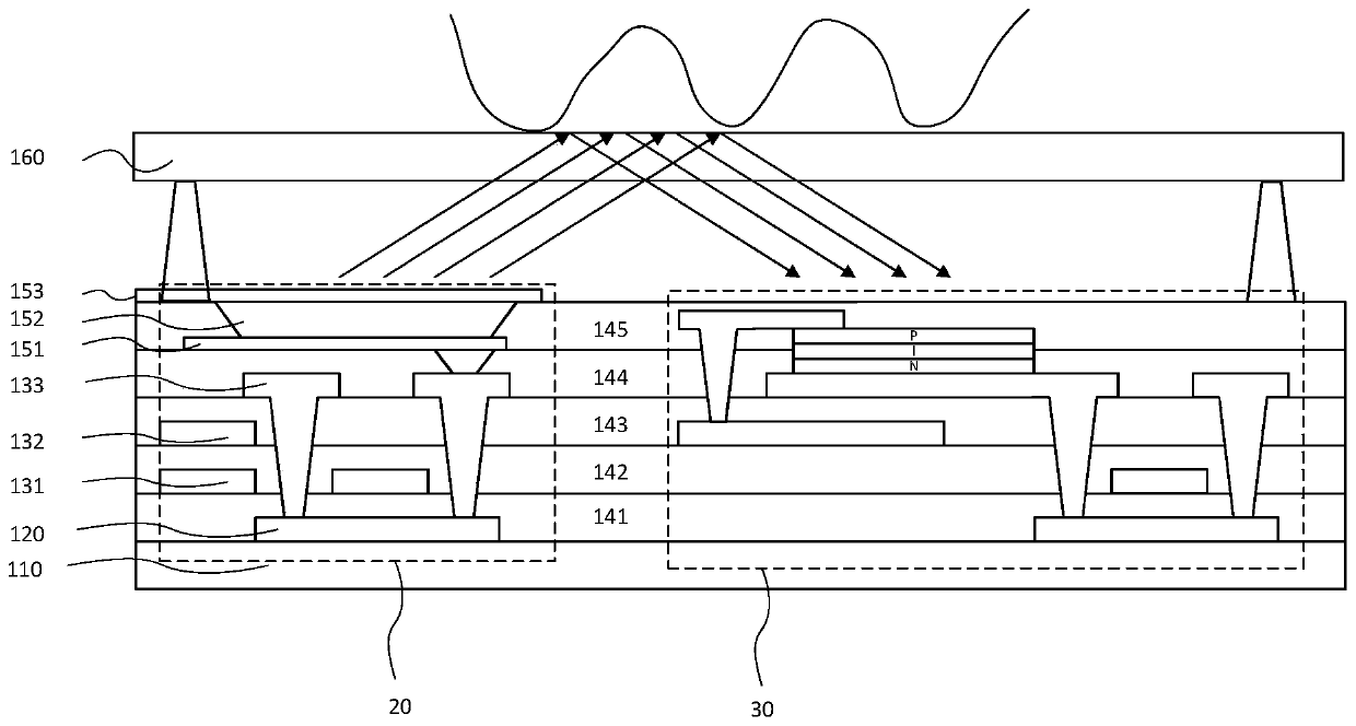
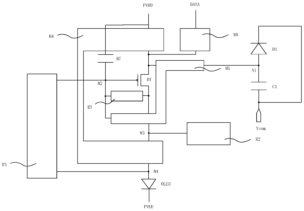
The embodiment of the invention provides a light sensation driving circuit. A display module group comprises a first power supply signal end, a driving transistor, an organic light-emitting element and a second power supply signal end which are connected in series. The driving transistor is used for generating driving current; the light sensing module group comprises a signal generation module anda reading module; the signal generation module is used for generating a light sensation signal under the action of illumination; the reading module is used for reading the light sensation signal; thesignal generation module comprises a light-sensitive diode and a first storage capacitor which are connected in series, and a first node arranged between the light-sensitive diode and the first storage capacitor; the first node is connected with the first electrode of the driving transistor; the signal generation module is electrically connected to the grid electrode of the driving transistor; the reading module is electrically connected between the second electrode of the driving transistor and the organic light-emitting element. The photosensitive driving circuit for fingerprint identification under the screen is integrated in the screen, and the fingerprint identification effect is improved while the fingerprint identification function is realized through the circuit design.

Description

【Technical field】 [0001] The invention relates to the field of display technology, in particular to a photosensitive driving circuit, a driving method thereof and a display device comprising the same. 【Background technique】 [0002] As consumption upgrades, consumers need display panels to integrate more functions, such as fingerprint recognition functions. Existing display panel fingerprint recognition functions are based on the fingerprint recognition chip set under the display panel, and the organic light-emitting display panel has a certain degree of light transmission. Fingerprint identification based on the principle of sex. However, this method requires an external fingerprint identification chip, which is complex in process, high in cost, and cannot realize full-screen fingerprint identification. However, in the prior art research on integrated fingerprint identification in the screen, it was found that due to the layout design of the organic light-emitting (OLED) d...

Claims


Application Information

Patent Timeline
IPC IPC(8): G09G3/3225G06K9/00
CPCG09G3/3225G06V40/1318
Inventor 周星耀高娅娜李玥杨康陈浩姚绮君
Owner WUHAN TIANMA MICRO ELECTRONICS CO LTD
Learn More