
Limit switch of control circuit

A limit switch and control circuit technology, applied in the direction of contact meshing, contact operating parts, etc., can solve the problems of damage, loose internal welding circuit, inconvenient maintenance, etc., to achieve convenient circuit connection, convenient maintenance, and tight connection. solid effect

Inactive Publication Date: 2019-10-01
新春仪表(常熟)有限公司
View PDF6 Cites 0 Cited by
  • Summary
  • Abstract
  • Description
  • Claims
  • Application Information

AI Technical Summary

Problems solved by technology

[0004] In order to solve the problem that the internal circuit connection of the limit switch of the existing control circuit is completed by welding, the limit switch will contact with the external drive device during use to generate vibration, and long-term use will make the internal welded circuit loose and damaged , while maintenance is very inconvenient, the purpose of the present invention is to provide a limit switch of the control circuit

Method used


Image

  • Limit switch of control circuit
  • Limit switch of control circuit
  • Limit switch of control circuit

Examples


Embodiment Construction

[0017] The implementation of the present invention will be illustrated by specific specific examples below, and those skilled in the art can easily understand other advantages and effects of the present invention from the contents disclosed in this specification.

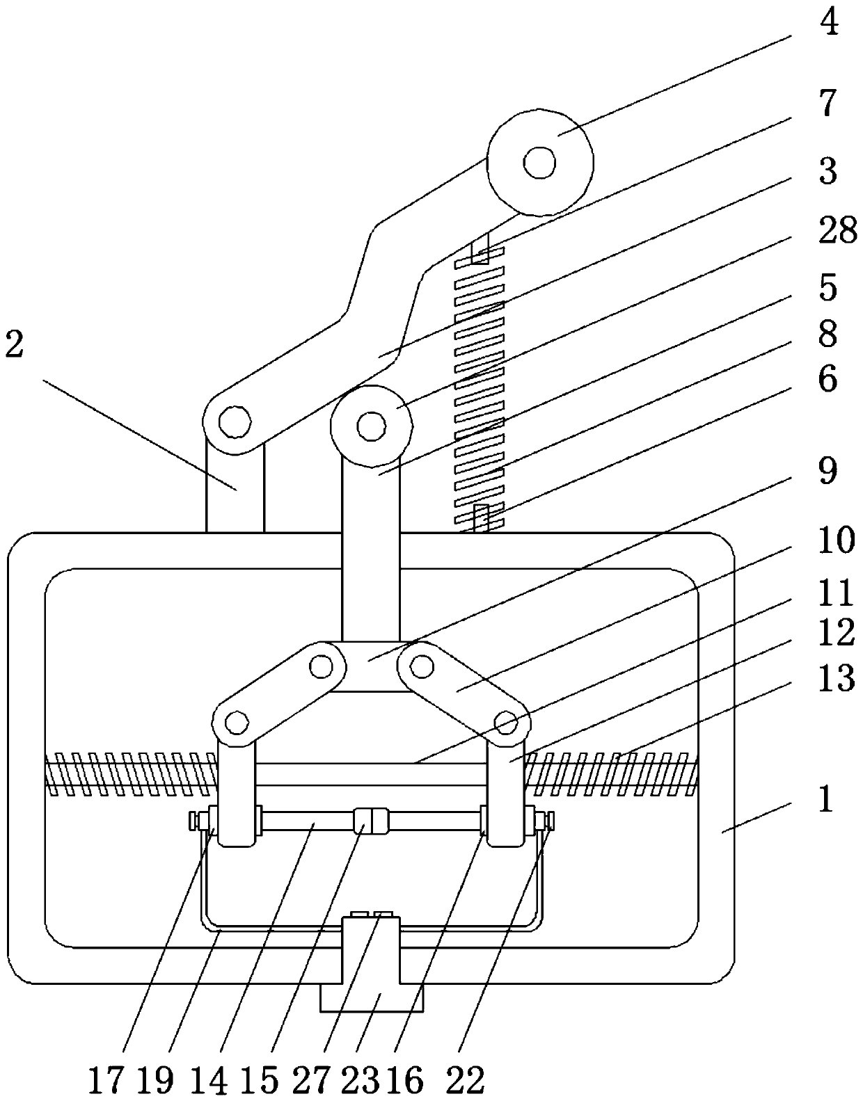
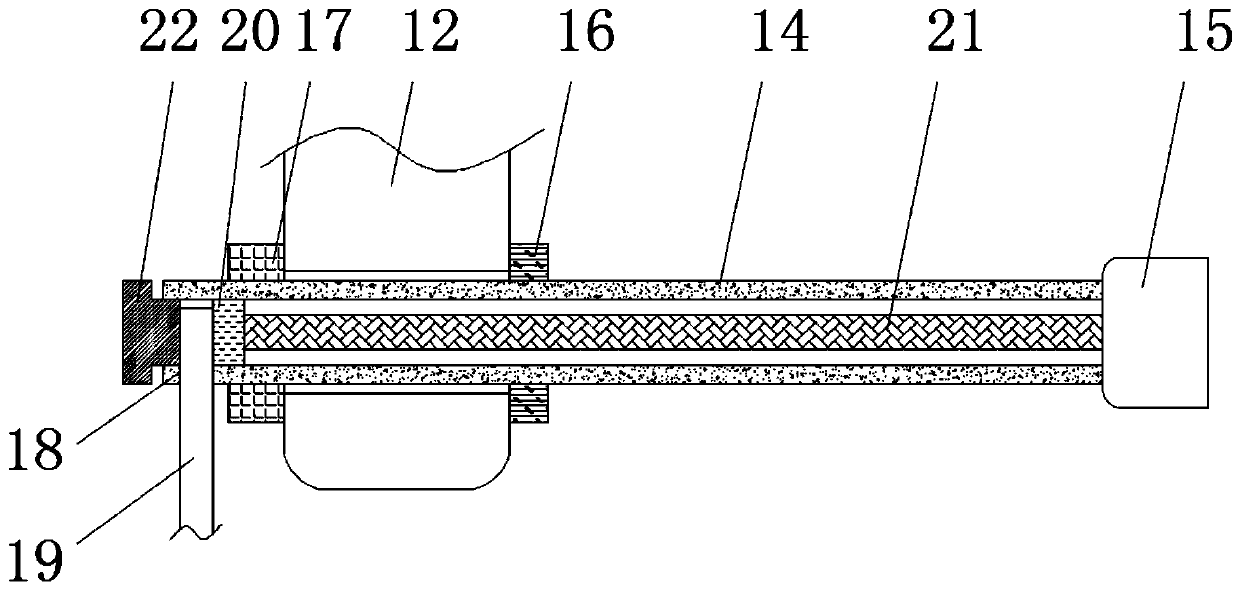
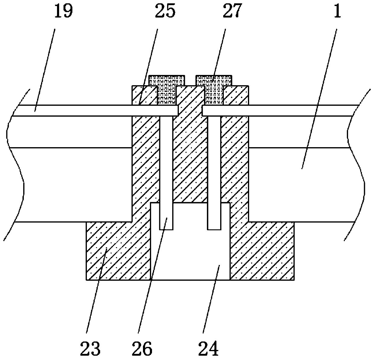
[0018] see Figure 1 to Figure 3 . It should be noted that the structures, proportions, sizes, etc. shown in the drawings attached to this specification are only used to match the content disclosed in the specification, for those who are familiar with this technology to understand and read, and are not used to limit the implementation of the present invention. Limiting conditions, so there is no technical substantive meaning, any modification of structure, change of proportional relationship or adjustment of size, without affecting the effect and purpose of the present invention, should still fall within the scope of the present invention. The disclosed technical content must be within the scope covered. At the sa...


PUM


Abstract

The invention discloses a limit switch of a control circuit. The limit switch comprises a casing. A surface of the casing is fixedly connected to a vertical plate and a first spring fixing column. A side wall of the vertical plate is movably connected to a pressing rod, a movable rod movably passes through a base surface of the casing, outer walls of a guiding rod are symmetrically and movably connected to two movable blocks, one end of each of two sleeves is fixedly connected to two metal blocks in a connection, outer walls of the sleeves are sleeved with first wire insertion holes, wires areinserted into inner walls of the first wire insertion holes, and a bottom of the casing is threadingly connected to a wire insertion column. The invention relates to the technical field of limiting switches. According to the limit switch, the problem that the connection of an internal circuit of a limit switch of an existing control circuit is completed by welding, the limit switch contacts withan external driving device to generate vibration during use, an internally welded circuit becomes loose after long-term use to be damaged, and the maintenance is very inconvenient is solved.

Description

technical field [0001] The invention relates to the technical field of limit switches, in particular to a limit switch for a control circuit. Background technique [0002] The limit switch is a commonly used small current master electrical appliance. Use the collision of the moving parts of the production machinery to make the contact move to realize the connection or break of the control circuit to achieve a certain control purpose. Usually, this type of switch is used to limit the position or stroke of the mechanical movement, so that the moving machinery will automatically stop, reverse movement, variable speed movement or automatic reciprocating movement according to a certain position or stroke. [0003] In the prior art, the internal circuit connection of the limit switch of the control circuit is completed by welding. The limit switch will contact with the external drive device during use and generate vibration. Long-term use will make the internal welded circuit loo...

Claims


Application Information

Patent Timeline
IPC IPC(8): H01H3/16H01H1/24
CPCH01H1/24H01H3/16
Inventor 顾建峰
Owner 新春仪表(常熟)有限公司
Learn More