Supercharge Your Innovation With Domain-Expert AI Agents!

Bi-stable electromagnetic mechanism

An electromagnetic mechanism and bistable technology, applied in the direction of protection switch operation/release mechanism, etc., can solve the problems of prone to safety accidents, reduce the service life of the electromagnet, and damage the electromagnet, so as to reduce production costs, prolong the service life, Reduce the effect of security incidents

Pending Publication Date: 2019-10-01
SUZHOU FUTURE ELECTRICAL APP
View PDF0 Cites 0 Cited by
  • Summary
  • Abstract
  • Description
  • Claims
  • Application Information

AI Technical Summary

Problems solved by technology

[0002] The circuit breaker is a switching device used to turn on or off the circuit, and it plays a role of protection and control in the power system; when the power system fails, the circuit breaker will perform the disconnection operation, and at the same time, a protection mechanism is required to make the power system in the event of a failure. , the circuit breaker cannot perform closing operation; at present, this kind of protection mechanism is mostly controlled by electromagnets, and the transition of the working state of the protection mechanism is completed through power-on or power-off to realize the restriction on the closing of the circuit breaker. In actual use, For the working state of limiting closing, the electromagnet needs to be continuously energized to maintain it. At the same time, the voltage input received by the electromagnet is very unstable, which is easy to cause damage to the electromagnet, which will reduce the service life of the electromagnet, and the working state will be affected by the electromagnetic The impact of iron is prone to safety accidents

Method used


Image

  • Bi-stable electromagnetic mechanism
  • Bi-stable electromagnetic mechanism
  • Bi-stable electromagnetic mechanism

Examples


Embodiment Construction

[0022] The present invention will be described in detail below in conjunction with the drawings.

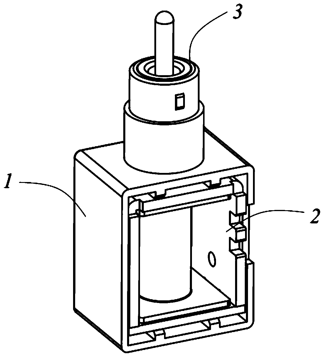
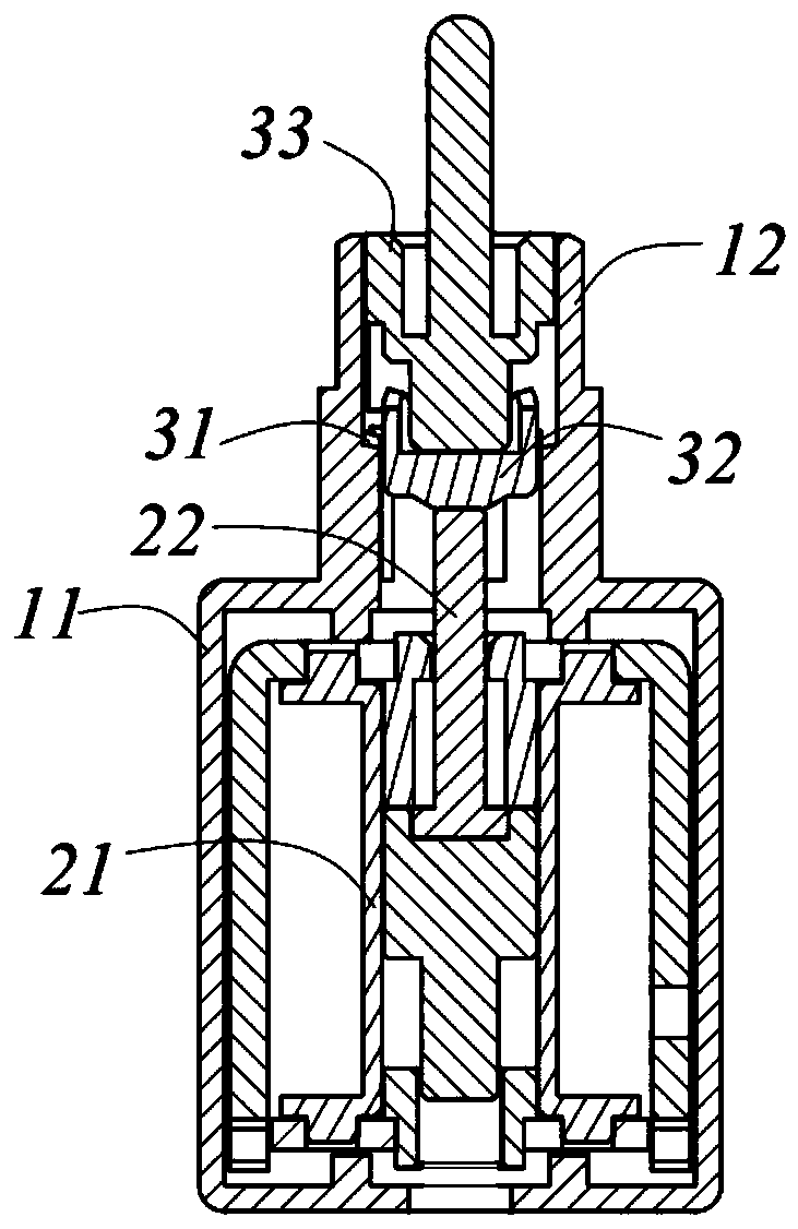
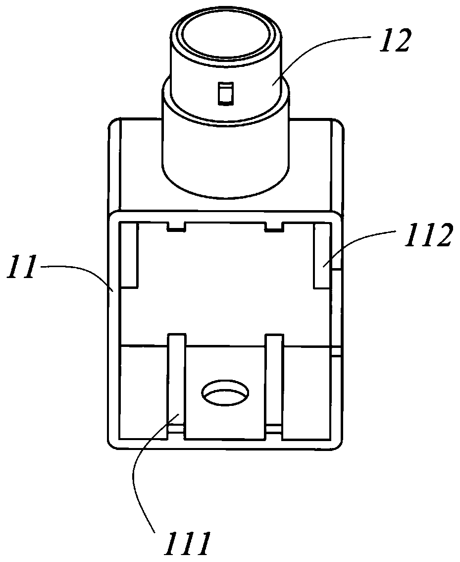
[0023] Such as figure 1 versus figure 2 A bistable electromagnetic mechanism shown includes a base 1, an electromagnetic component 2 arranged in the base 1, and a limit component 3 driven by the electromagnetic component 2. The limit component 3 includes a positioning member 31 and a driving member 32 and a rotating member 33. The positioning member 31 is provided with a working high position and a working low position. The driving member 32 drives the rotating member 33 to rotate in the positioning member 31 and stay at the working high position or the working low position for positioning; The electromagnetic assembly 2 makes the driving member 32 move up and down. The electromagnetic component 2 is energized and works only in the transitional state from working high position to working low position and working low position to working high position, and the electromagnetic compone...


PUM


Abstract

The invention relates to a bi-stable electromagnetic mechanism, which includes a base, an electromagnetic assembly arranged in the base and a limit assembly driven by the electromagnetic assembly. Thelimit assembly includes a positioning member, a driving member and a rotating member. The positioning member is provided with a high working position and a low working position. The driving member drives the rotating member to rotate in the positioning member and stop at the high working position or the low working position for positioning. The electromagnetic assembly makes the driving member move up and down. By adopting the protection mechanism, under the closed state of a circuit breaker, limiting is carried out by a mechanical structure, and the electromagnetic assembly is not powered on. The electromagnetic assembly is powered on to work only in transition states from a working state to a non-working state and from a non-working state to a working state. Therefore, the stability ofthe working state of the protection mechanism is improved, the production cost is reduced, the service life of the electromagnetic assembly is prolonged, and the occurrence of safety accidents in thecircuit system is reduced.

Description

Technical field [0001] The present invention relates to the technical field of circuit breaker control, in particular to a bistable electromagnetic mechanism used in an electric operating mechanism. Background technique [0002] A circuit breaker is a switch device used to connect or disconnect a circuit, which plays a role of protection and control in the power system; and when the power system fails, the circuit breaker will perform the opening operation, and a protection mechanism is required to make it , The circuit breaker cannot be closed; at present, this kind of protection mechanism is mostly controlled by electromagnets, which realizes the restriction on the closing of the circuit breaker by energizing or de-energizing to complete the transition of the working state of the protection mechanism. In actual use, Regarding the working state that restricts closing, the electromagnet needs to be continuously energized to maintain it. At the same time, the voltage input receive...

Claims


Application Information

Patent Timeline
Patent Type & Authority Applications(China)
IPC IPC(8): H01H71/24
CPCH01H71/24
Inventor 毛海锋丁冬明
Owner SUZHOU FUTURE ELECTRICAL APP
Features
  • R&D
  • Intellectual Property
  • Life Sciences
  • Materials
  • Tech Scout
  • Unparalleled Data Quality
  • Higher Quality Content
  • 60% Fewer Hallucinations
Learn More