
Novel electronic cam pin-inserting mechanism

A technology of electronic cams and pins, applied in the manufacture of contacts, assembly/disassembly of contacts, etc., can solve the problems of complex structures and methods, low production efficiency, inflexibility, etc., and achieve simple structures and methods, and convenient machine maintenance , Flexible and precise control effect

Pending Publication Date: 2019-10-01
江苏倚信自动化设备有限公司
View PDF0 Cites 0 Cited by
  • Summary
  • Abstract
  • Description
  • Claims
  • Application Information

AI Technical Summary

Problems solved by technology

[0004] The purpose of the present invention is to provide a new type of electronic cam pin mechanism to solve the problem of the traditional mechanical cam pin mechanism proposed in the above-mentioned background technology. Easy to adjust, only one specification product can be made, inflexible, no commonality, slow pin insertion speed, low production efficiency, complex structure and method, unstable high-speed mechanical operation, and cannot meet the existing production needs

Method used


Image

  • Novel electronic cam pin-inserting mechanism
  • Novel electronic cam pin-inserting mechanism
  • Novel electronic cam pin-inserting mechanism

Examples


Embodiment Construction

[0028] The following will clearly and completely describe the technical solutions in the embodiments of the present invention with reference to the accompanying drawings in the embodiments of the present invention. Obviously, the described embodiments are only some, not all, embodiments of the present invention. The specific embodiments described here are only used to explain the present invention, not to limit the present invention. Based on the embodiments of the present invention, all other embodiments obtained by persons of ordinary skill in the art without making creative efforts belong to the protection scope of the present invention.

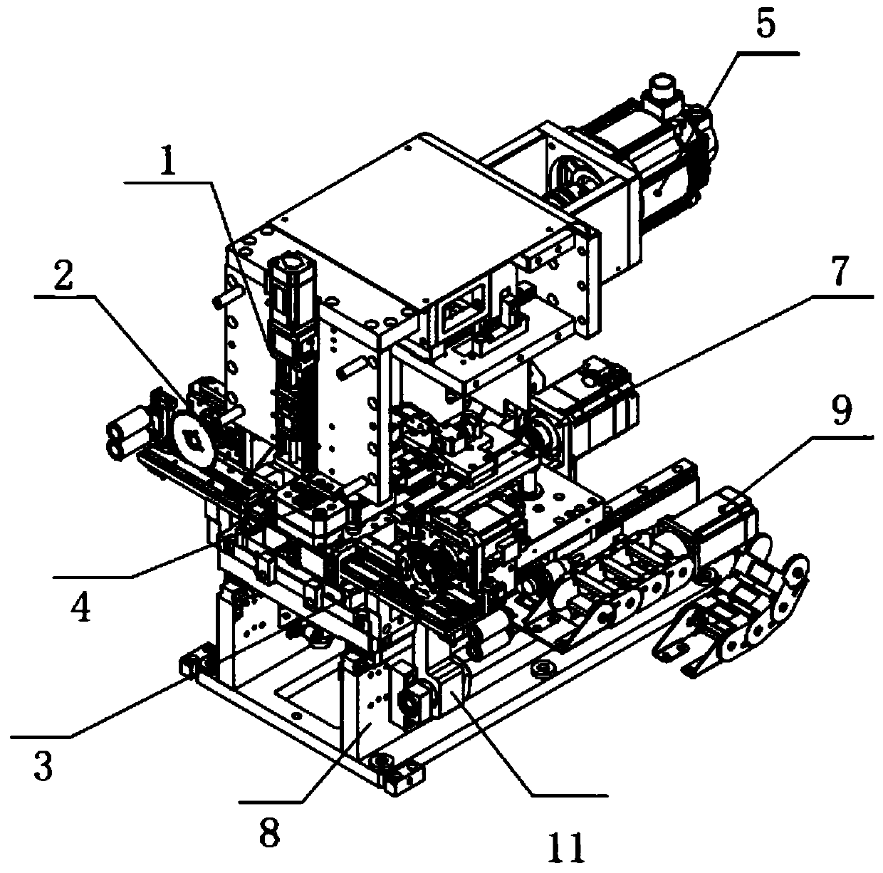
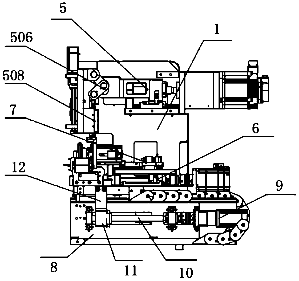
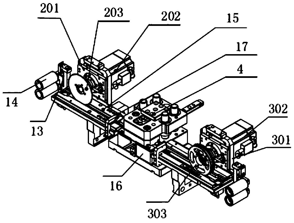
[0029] The present invention provides such Figure 1-7 A new type of electronic cam pin insertion mechanism shown includes a first mounting frame 1, a left feeding mechanism 2 is provided on the left side of the front end of the first mounting frame 1, and a left feeding mechanism 2 is provided on the front end right side of the first mou...


PUM


Abstract

The invention discloses a novel electronic cam pin-inserting mechanism, including a first mounting frame. A left feeding mechanism is arranged on the left side of the first mounting frame, and a rightfeeding mechanism is arranged on the right side. A cutting mold is arranged between the left feeding mechanism and the right feeding mechanism. A cutting mechanism is arranged on the back side of thefirst mounting frame. A pressing mechanism is arranged in the middle of the first mounting frame. A pin inserting mechanism is arranged on the pressing mechanism. The first mounting frame is connected in a sliding manner with a second mounting frame. A first servo motor is fixed at the rear end of the second mounting frame. A first screw rod is fixed at the end of the output shaft of the first servo motor through a coupling. The first screw rod is in transmission connection with a first mounting block. A first connecting plate is fixed on the first mounting block. The first connecting plate is fixedly connected with the first mounting frame. Through the structure, pin inserting can be carried out on different types of products. The structure and the method are simple. The mechanism can becontrolled flexibly and precisely, and runs stably and fast. The machine is easy to adjust during maintenance.

Description

technical field [0001] The invention belongs to the technical field of pin insertion mechanisms, and in particular relates to a novel electronic cam pin insertion mechanism. Background technique [0002] The cam pin insertion mechanism is used for high-speed and continuous pin insertion of connector products. The structure is a single-drive multi-cam pair mechanism composed of multiple disc cams, swing rods, and moving platforms. By matching the angular displacement and stroke relationship timing of each cam , so as to achieve high-speed cycle pin. [0003] The traditional mechanical cam pin insertion mechanism cannot be flexibly and accurately controlled due to its fixed size. It can only correspond to one machine with a specific material number. It is inconvenient to maintain and adjust. It can only make products of one specification. It is not flexible, has no commonality, and the pin insertion speed is slow. The production efficiency is low, and the structure and method...

Claims


Application Information

Patent Timeline
IPC IPC(8): H01R43/20H01R43/16
CPCH01R43/20H01R43/16
Inventor 赵海兵邱军良满军
Owner 江苏倚信自动化设备有限公司
Learn More