Supercharge Your Innovation With Domain-Expert AI Agents!

Apparatus for detaching surgical blades

A scalpel and blade technology, applied in the field of equipment, tools and systems, and devices, can solve the problems of difficult tool manufacturing process, unreusable, high reliability and high failure rate, etc.

Inactive Publication Date: 2019-10-01
AUNEX PTY LTD
View PDF9 Cites 0 Cited by
  • Summary
  • Abstract
  • Description
  • Claims
  • Application Information

AI Technical Summary

Problems solved by technology

Containing a large number of moving parts can make the tooling process difficult
Another type of blade removal tool is described in International Patent Publication No. WO2004093706A1, however this tool described in International Patent Publication No. WO2004093706A1 is specifically designed to remove only one blade and then it cannot be used again, so , which is impractical in many cases
Another tool for removing scalpel blades is described in U.S. Patent No. 5,875,533, however, this tool described in U.S. Patent No. 5,875,533 is only capable of accommodating a limited range of scalpel blades and handles
Some other problems associated with currently known blade removal devices relate to the reliability of the prior art devices and the high failure rate due to excessive friction and seizing

Method used


Image

  • Apparatus for detaching surgical blades
  • Apparatus for detaching surgical blades
  • Apparatus for detaching surgical blades

Examples


Embodiment Construction

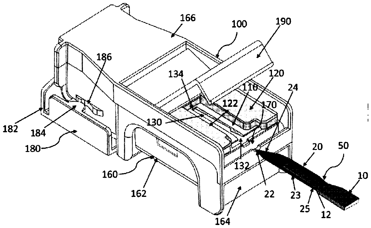
[0047] refer to Figures 2 to 7 , shows a first embodiment of the invention in the form of a blade removal device 100 . The blade removal device 100 includes a flexible blade separation member 110 (preferably comprising a flexible polymer material) disposed alongside a rigid polymer backplate 120 . In particular, the back plate 120 is disposed continuously over the flexible blade separation member 110 so as to constrain bending of the blade separation member 110 and only allow downward bending of the separation member 110 during use.

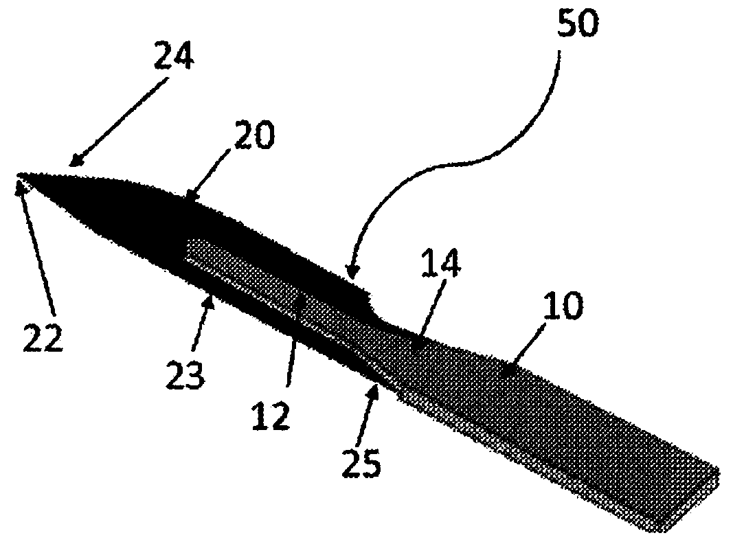
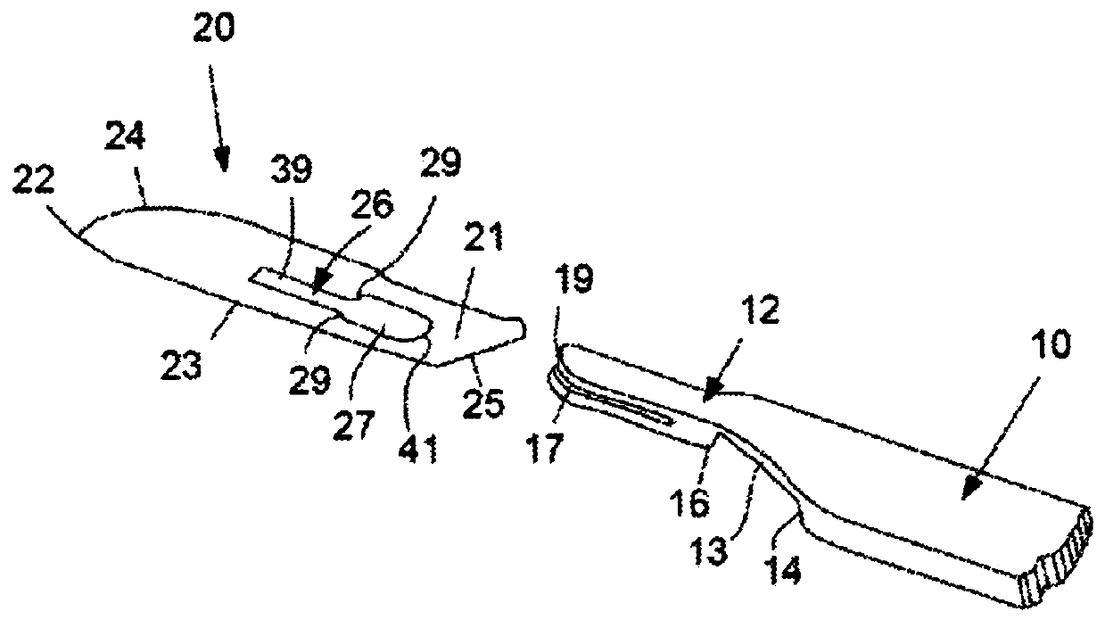
[0048] The separating member 110 is formed with a longitudinal opening 130 extending between a front end 132 and a rear end 134 . The opening 130 is wide enough to pass the tang 12 but narrow enough to block the passage of the blade 20 . An opening or slot 130 is defined by the separation member 110, and the opening or slot 130 is shaped for placing the tang 12 within the opening 130, which causes the mounted blade 20 to be positioned near the...


PUM


Abstract

An apparatus for detaching a blade from a scalpel handle is provided. The blade has a cutting portion and a heel portion and is removably mounted on a tang of the scalpel handle. The apparatus has a flexible blade detachment member with a stepped portion for engaging the heel of the blade as the handle is withdrawn and a leading angled portion. A backing member is provided with the detachment member being arranged adjacent the backing member so that during use the detachment member flexes in only one direction, away from the mounting tang in response to force applied by the handle to the leading angled portion thereby causing the blade and the handle to be separated and detached relative to each other. Upon withdrawing the tang from the opening, the stepped portion engages the heel of theblade resulting in detachment of the blade from the tang.

Description

technical field [0001] The present invention relates generally to devices, apparatus, tools and systems for removing used disposable surgical scalpel blades from scalpel handles and for safely disposing of such contaminated blade. Background technique [0002] Any reference to a method, device or document of prior art is not to be considered as any evidence or admission that such method, device or document forms part of the common general knowledge. [0003] As is well known, modern surgical scalpel blades are disposable and are designed to fit over a reusable handle to form a scalpel. figure 1 and Figure 1A A commercially available scalpel 50 comprising a reusable handle 10 and disposable blade 20 is shown. Surgical blade 20 comprises a sharp point 22, cutting edge 24 and a shank 23, wherein cutting edge 24 is positioned at the front portion of blade, and shank 23 extends to the rear portion 21 of blade 20, and the rear portion 21 of this blade 20 forms blade 20 of the...

Claims


Application Information

Patent Timeline
Patent Type & Authority Applications(China)
IPC IPC(8): A61B17/3217A61B17/3211A61B17/32A61B50/36A61B17/3213B65D83/10B65D25/10
CPCA61B17/3213A61B17/3217A61B50/362B65D25/10B65D83/10
Inventor 金·希亚·奎
Owner AUNEX PTY LTD
Features
  • R&D
  • Intellectual Property
  • Life Sciences
  • Materials
  • Tech Scout
  • Unparalleled Data Quality
  • Higher Quality Content
  • 60% Fewer Hallucinations
Learn More