
Handle with removable disposable surgical blade and blade removal system including disposal container

a technology of surgical blades and disposal containers, which is applied in the field of surgical blade systems, can solve the problems of inability to maintain such tolerances, slight wobbling between the blade and the handle, and manufacturing difficulties, and achieve the effect of easy removal of the handl

Inactive Publication Date: 2007-07-05
PETERSEN THOMAS D
View PDF32 Cites 27 Cited by
  • Summary
  • Abstract
  • Description
  • Claims
  • Application Information

AI Technical Summary

Benefits of technology

[0006] (1) In a first aspect of the present invention, a handle is provided that includes a distal end with a recess sized to receive the proximal end of a blade assembly. As will be better understood in conjunction with description of the blade assembly, the recess includes a proximal notch as well as opposed inwardly facing distal ridges obliquely angled with respect to the axis of elongation of the handle and designed to engage grooves in the blade assembly to assist in maintaining the blade assembly and handle in assembled relation.
[0008] (3) The fitting also includes side faces having opposed grooves obliquely disposed so that they are engaged by the distal ridges within the handle recess to assist in locking the blade assembly to the handle. The fitting also includes an upwardly and proximally extending catch that engages a distal surface on the handle to assist in locking the blade assembly to the handle.
[0010] (5) An integral part of the present invention consists of the blade removal system that permits the blade assembly to be easily and effectively removed from the handle without any danger of cutting or puncturing the fingers or hands of the surgeon. The blade removal system includes a container having a removable lid, with the lid having a centrally located, generally rectangular opening therein leading to a short passageway sized and configured to receive the blade assembly therein. The blade assembly may be inserted into the recess until the fitting engages within a rectangular opening therein. In that orientation, the handle may be pivoted to unlock the blade assembly from the handle, whereupon the blade assembly falls through the opening and into the container. In the preferred embodiment of the present invention, the container is made of a transparent plastic material permitting easy viewing of the blade assembly as removed from the handle and located therein.
[0015] It is a yet further object of the present invention to provide a blade removal system in which the blade assembly may easily be removed from the handle without danger to the surgeon.
[0016] It is a still further object of the present invention to provide such a blade removal system in which the blade assembly may be inserted into an opening in the lid of a disposal container and the handle may be pivoted to easily unlock the blade assembly from the handle, resulting in the blade assembly falling into the interior of the container.

Problems solved by technology

In that system, exacting tolerances in the tapers of the recess in the fitting and the protrusion on the distal end of the handle created manufacturing difficulties.
Applicant found that manufacturers were unable to maintain such tolerances, thereby resulting in slight wobbling between the blade and handle.
An additional concern arose in that there were circumstances during which the blade could inadvertently detach from the handle or loosen from it during use.
This technique introduced danger to the surgeon since his or her fingers would be quite close to the actual blade edge, thereby creating the possibility of puncture or cutting of the surgeon's fingers, though inadvertently.

Method used


Image

  • Handle with removable disposable surgical blade and blade removal system including disposal container
  • Handle with removable disposable surgical blade and blade removal system including disposal container
  • Handle with removable disposable surgical blade and blade removal system including disposal container

Examples


Embodiment Construction

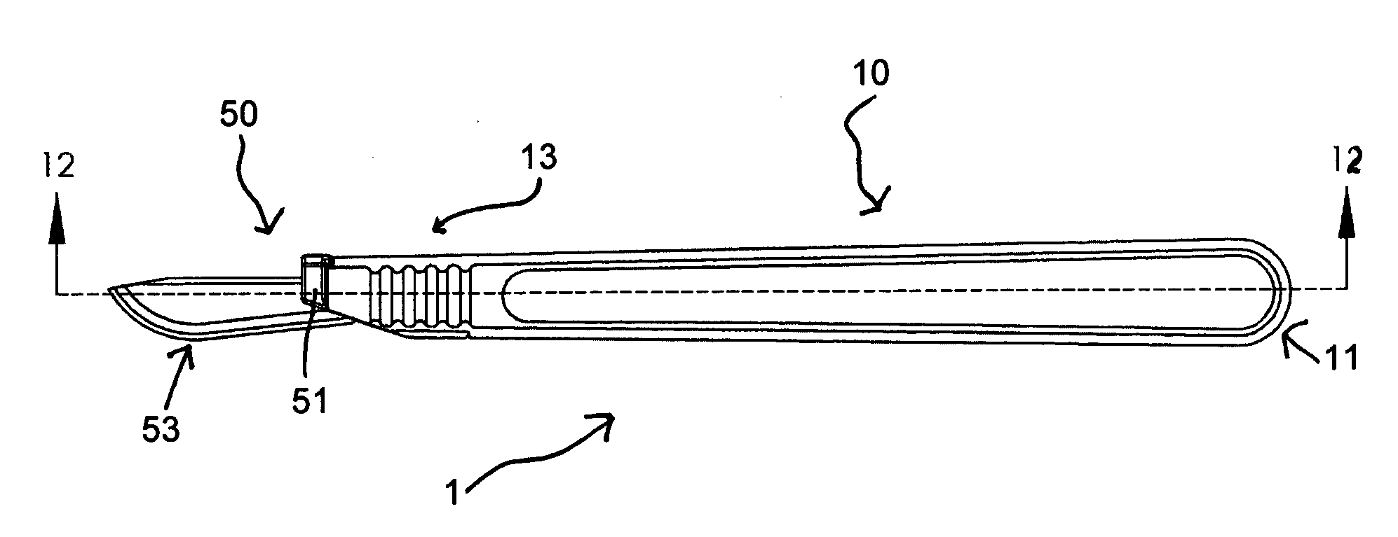
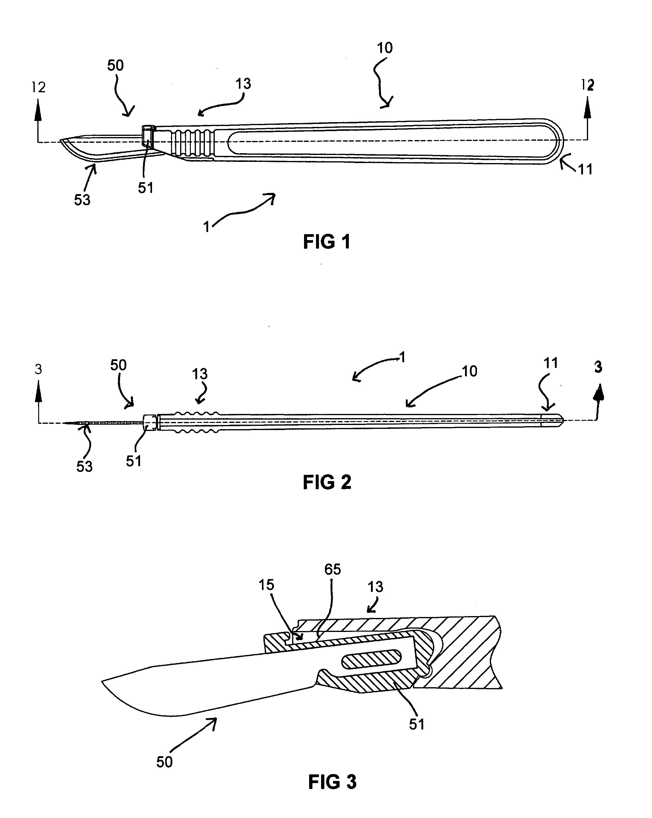
[0037] With reference, first, to FIG. 1, the present invention is generally designated by the reference numeral 1 and is seen to include a handle 10 and a blade assembly 50. The handle 10 includes a proximal end 11 and a distal end 13. The blade assembly includes a proximally located fitting 51 and a distal blade portion 53. Many of these features are also seen in FIG. 2.

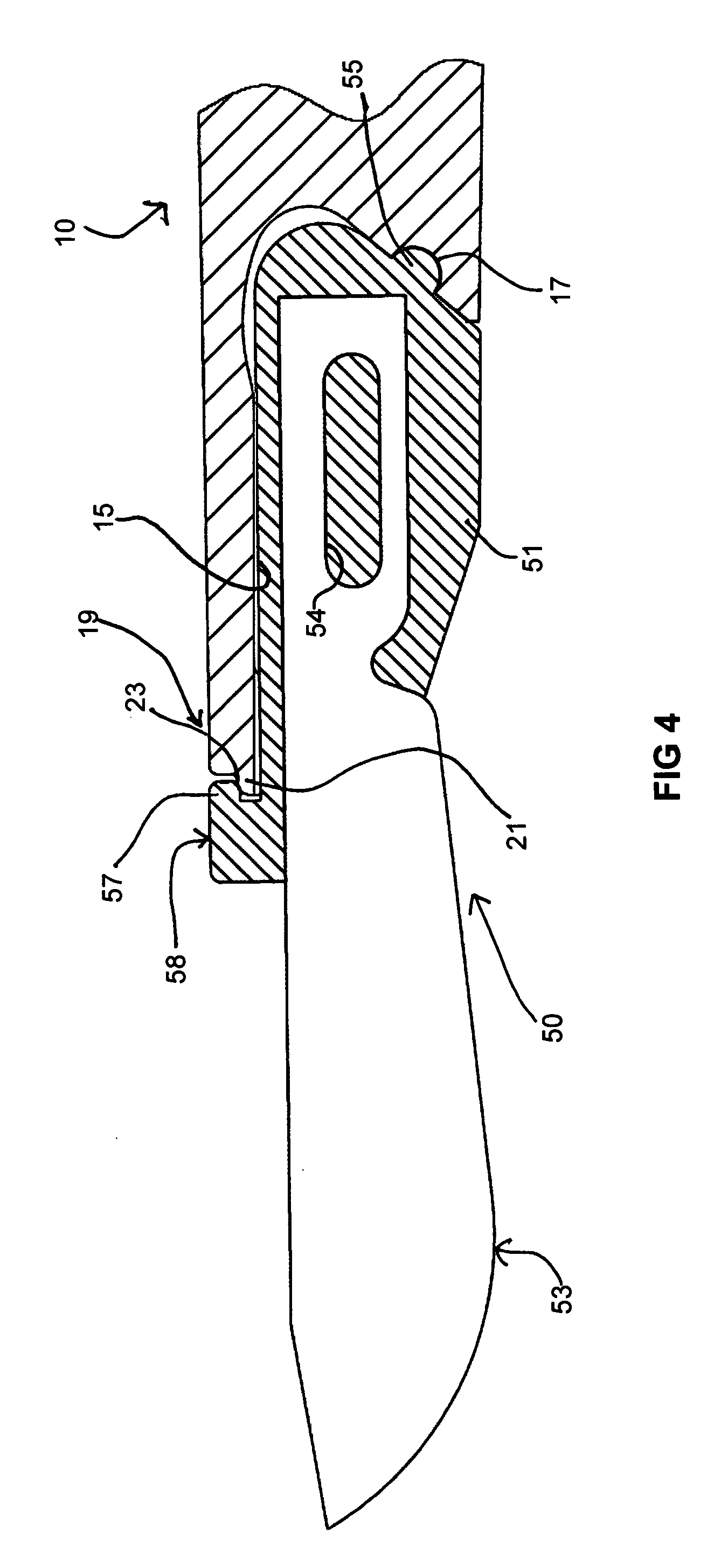
[0038] With reference to FIG. 3, the distal end 13 of the handle 10 includes a recess 15 sized and configured to receive the fitting 51 releasably fixed therein. With reference to FIG. 4, it is seen that the recess 15 includes a proximal notch 17 sized to receive a protrusion 55 at the proximal end of the fitting 51. Also seen in FIG. 4 is a distal surface 19 on the handle 10 that includes a distally directed tang 21 as well as a shoulder 23. The fitting 51 includes a distally directed catch 57 that engages over the tang 21 and into the shoulder 23 to assist in locking the blade assembly 50 into the recess 15 of th...


PUM


Abstract

A surgical blade includes a handle with a recess sized to receive the proximal end of a blade assembly. The recess includes a notch as well as opposed facing distal ridges designed to engage elevated surfaces in the blade assembly to maintain the blade assembly and handle assembled. The blade assembly includes a blade portion and a fitting having a protrusion sized to be received in the proximal notch of the recess in the handle when the blade portion is assembled to the handle. The fitting also includes side faces having opposed elevated surfaces obliquely disposed so that they are engaged by the distal ridges within the handle recess. The fitting also includes an upwardly extending catch that engages a distal surface on the handle to assist in locking the blade assembly to the handle. The recess of the handle includes inner tapered surfaces. The side faces of the fitting are tapered to the same degree so that as the fitting is pushed upwardly within the recess, the side faces of the fitting engage the lateral inner surfaces of the recess to provide an interference fit therebetween. A blade removal system permits the blade assembly to be removed from the handle without any danger of cutting or puncturing the fingers or hands of the surgeon. The system includes a container having a removable lid, with the lid having an opening leading to a short passageway receiving the blade assembly. The blade assembly may be inserted into the recess until the fitting engages within a rectangular opening therein. In that orientation, the handle may be pivoted to unlock the blade assembly from the handle.

Description

[0001] The present invention relates to a handle with removable disposable surgical blade and blade removal system including disposal container. The present invention constitutes a significant improvement over Applicant's prior invention as disclosed and claimed in U.S. Pat. No. 6,500,187, issued Dec. 31, 2002. The disclosure of Applicant's prior patent is incorporated by reference herein along with all of the prior art cited during the prosecution thereof.BACKGROUND OF THE INVENTION [0002] Applicant's prior invention constituted an effective and useful surgical saw blade system including a scalpel detachably mountable to an elongated handle and with the scalpel easily disposable. However, several minor deficiencies in Applicant's prior invention combined together to lead Applicant to the conclusion that improvements could be made to create an easier to use, simpler and more effective blade-handle system. In Applicant's prior invention, the scalpel blade has a fitting with a proxima...

Claims


Application Information

Patent Timeline
Patent Type & Authority Applications(United States)
IPC IPC(8): A61B17/32
CPCA61B17/3213A61B19/0288A61B17/3217A61B50/362
Inventor PETERSEN, THOMAS D.
Owner PETERSEN THOMAS D
Learn More