Microsurgical cutting instruments

a cutting instrument and micro-sharpening technology, applied in the field of self-sharpening knives, can solve the problems of inability to use metals to fabricate micro-knife of atomic level dimensions, inability to use metals, and inability to achieve the effect of atomic level cutting accuracy and low cost of manufacturing process

Inactive Publication Date: 2009-07-09
MYNOSYS CELLULAR DEVICES INC
View PDF25 Cites 29 Cited by
  • Summary
  • Abstract
  • Description
  • Claims
  • Application Information

AI Technical Summary

Benefits of technology

[0018]The microknives described herein can be mounted on handles for use as hand held instruments, attached to catheters, and/or attached to micromanipulators. The knives are suitable for manual operation or robotic control. The cost of the manufacturing process is also sufficiently low that

Problems solved by technology

Even with diamond, the hardest material that exists, it is just a matter of time before atoms are worn away from the cutting edge and it becomes dull.
Although diamond knives can be re-sharpened, it is difficult, requiring special skill and tools.
However, the references referred to above, teach of traditional fabrication techniques and do not teach knives having a sharpness measured at the atomic level.
In fact, the use of metals to fabricate a micro-knife of atomic level dimensions is not possible because metals undergo plastic deformation at the stresses that will be encountered in cutting tissue or other materials at the atomic level.
For example, a micro-knife having, dimensions 1 mm long, 0.020 mm thick, and 0.5 mm wide (and fabricated t

Method used


Image

  • Microsurgical cutting instruments
  • Microsurgical cutting instruments
  • Microsurgical cutting instruments

Examples


Embodiment Construction

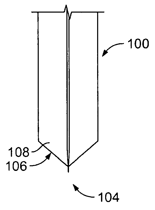
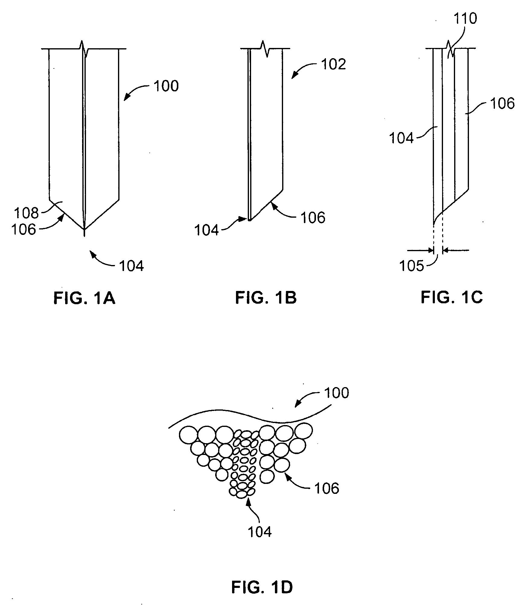
[0046]FIG. 1A shows a cross sectional view of one variation of a microsurgical blade 100. The thin layer, or region of cutting, region 104 is supported on both sides by a thicker layer of a support material 106. As noted above, the cutting material 104 is a region in the knife that has a relatively low wear rate as compared to the supporting material 106. In one variation, the cutting region 104 is a discrete layer that is separate (clearly distinct) from any adjacent layer. In additional variations, the region 104 may transition to a support region 106 (having a higher wear rate). In the latter case, a transition region 110 will be located at the interface between Cutting and support regions. In another variation, mechanical support for the cutting layer may be entirely provided by a transition region, without another “support material.”

[0047]FIG. 1B shows a variation of a self-sharpening microsurgical knife 102 having a cutting region 104 supported on a single side by a supporting...


PUM

PropertyMeasurementUnit
Diameteraaaaaaaaaa
Thicknessaaaaaaaaaa
Shapeaaaaaaaaaa

Abstract

The present invention relates to methods and apparatus for self-sharpening micro surgical blades, knives and assemblies.

Description

CROSS-REFERENCE TO RELATED APPLICATIONS[0001]This application is a continuation of International PCT Application No. PCT / US2007 / 061701 filed Feb. 6, 2007 which claims benefit of priority to U.S. Provisional Application No. 60 / 765,803 filed Feb. 6, 2006, both applications of which are incorporated herewith in their entirety.BACKGROUND OF THE INVENTION[0002]The concept of a self-sharpening knife comes originally from observations of the incisors of rats. These teeth consist of a very hard, but very thin, front layer which is mechanically supported by a much thicker, but softer, tooth body. The sharpness of the cutting edge comes from the thinness of the hard front layer. The softer material wears away faster such that a steady state profile is maintained in normal use (gnawing) in which the tooth body slopes down away from the thin hard front cutting edge. It can never get dull because the hard layer has the same thickness down the whole length of the tooth, and it is this thickness t...

Claims


Application Information

Patent Timeline
IPC IPC(8): A61B17/32
CPCA61B17/3211B24B37/00B24B3/60A61B2017/00831Y10T83/97
Inventor KELLER, CHRISTOPHER GUILD
Owner MYNOSYS CELLULAR DEVICES INC
Why Eureka
Try Eureka