Positioning punching tool

A tooling and shifting device technology, which is applied to workbenches, manufacturing tools, metal processing equipment, etc., can solve the problems of dust and debris affecting the line of sight, low drilling efficiency, and inconvenient operation

Pending Publication Date: 2019-10-08
中国人民解放军63926部队
View PDF0 Cites 0 Cited by
  • Summary
  • Abstract
  • Description
  • Claims
  • Application Information

AI Technical Summary

Problems solved by technology

[0003] In this regard, the traditional method is generally to climb up the site with the help of a ladder, and then use a drilling tool such as an electric hammer to drill holes, but this method is inconvenient to operate, and the dust debris generated by drilling can easily enter

Method used


Image

  • Positioning punching tool

Examples


Embodiment Construction

[0024] In order to enable those skilled in the art to better understand the technical solutions of the present invention, the present invention will be further described in detail below in conjunction with the accompanying drawings and specific embodiments.

[0025] The "several" mentioned in this article refers to a number with an indeterminate number, usually more than two; and when "several" is used to indicate the quantity of certain components, it does not indicate the relationship between these components in terms of quantity.

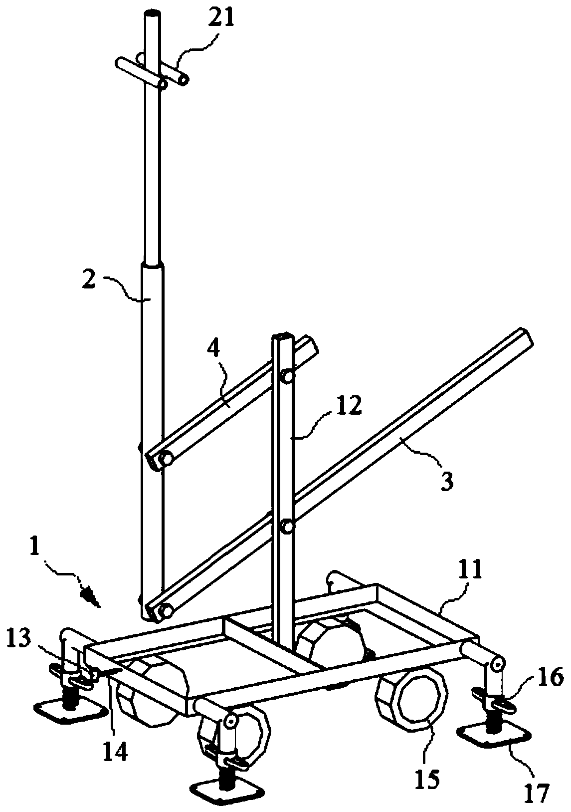
[0026] Please refer to figure 1 , figure 1 It is a structural schematic diagram of a specific embodiment of the positioning and punching tool provided by the present invention.

[0027] Such as figure 1 As shown, the present invention provides a positioning punching tool, including a base 1, a lifting beam 2 and an operating beam 3, the operating beam 3 is hinged to the base 1, the lifting beam 2 is connected to the operating beam 3, and the li...


PUM


Abstract

The invention discloses a positioning punching tool. The tool comprises a base, a lifting beam and a control beam, the control beam is hinged to the base, and the lifting beam is connected with the control beam and provided with a mounting position for installation of a punching device; when the control beam rotates, the lifting beam can be driven to ascend and descend. During specific operation,the punching device can be fixed to the mounting position, the control beam is rotated to drive the lifting beam to be lifted, and a top plate of a room is punched; in the whole process, field personnel do not directly operate the punching device and do not need to always raise the head, dust, debris and the like which are generated during punching do not easily influence field personnel, and thesafety of the punching process can be improved; field personnel do not need to go up and down the stairs with the help of a trestle ladder in the punching process, when the punching position needs tobe adjusted, the position of the positioning punching tool is directly adjusted, and the punching efficiency is high.

Description


Claims


Application Information

Patent Timeline
Owner 中国人民解放军63926部队
Why Eureka
Try Eureka