Railway vehicle and underframe structure thereof

A rail vehicle and underframe technology, applied in the field of rail vehicles, can solve the problems of difficult to meet the collision requirements, reduce the strength and stiffness of the car body, and achieve the effect of improving the carrying capacity and increasing the carrying capacity

Active Publication Date: 2019-10-08
ZHUZHOU ELECTRIC LOCOMOTIVE CO
View PDF5 Cites 10 Cited by
  • Summary
  • Abstract
  • Description
  • Claims
  • Application Information

AI Technical Summary

Problems solved by technology

In order to facilitate passengers to get on and off the car and reduce the moving distance of passengers, the doors and stairs are placed in the middle of the vehicle, but this will further reduce the strength and stiffness of the car body, making it difficult to meet the collision requirements of the EN 15227 standard

Method used


Image

  • Railway vehicle and underframe structure thereof
  • Railway vehicle and underframe structure thereof
  • Railway vehicle and underframe structure thereof

Examples


Embodiment Construction

[0036] In view of this, the core of the present invention is to provide an underframe structure of a rail vehicle to improve the strength and rigidity of the underframe. Another core of the present invention is to provide a rail vehicle having the above undercarriage structure.

[0037] In order to enable those skilled in the art to better understand the solution of the present invention, the present invention will be further described in detail below in conjunction with the accompanying drawings and specific embodiments.

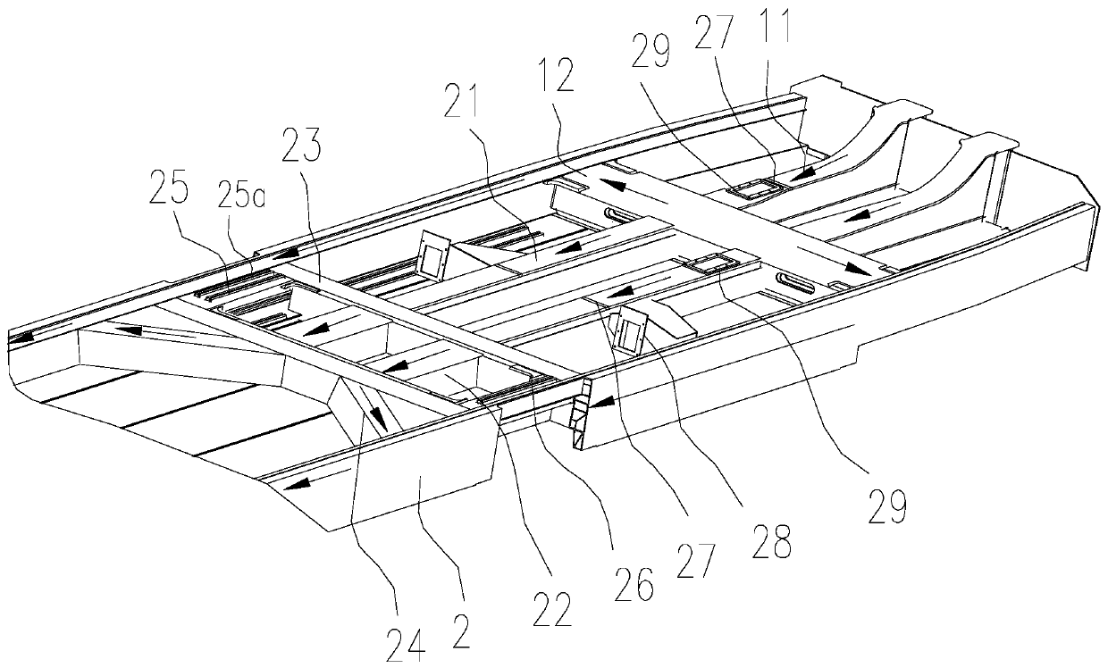
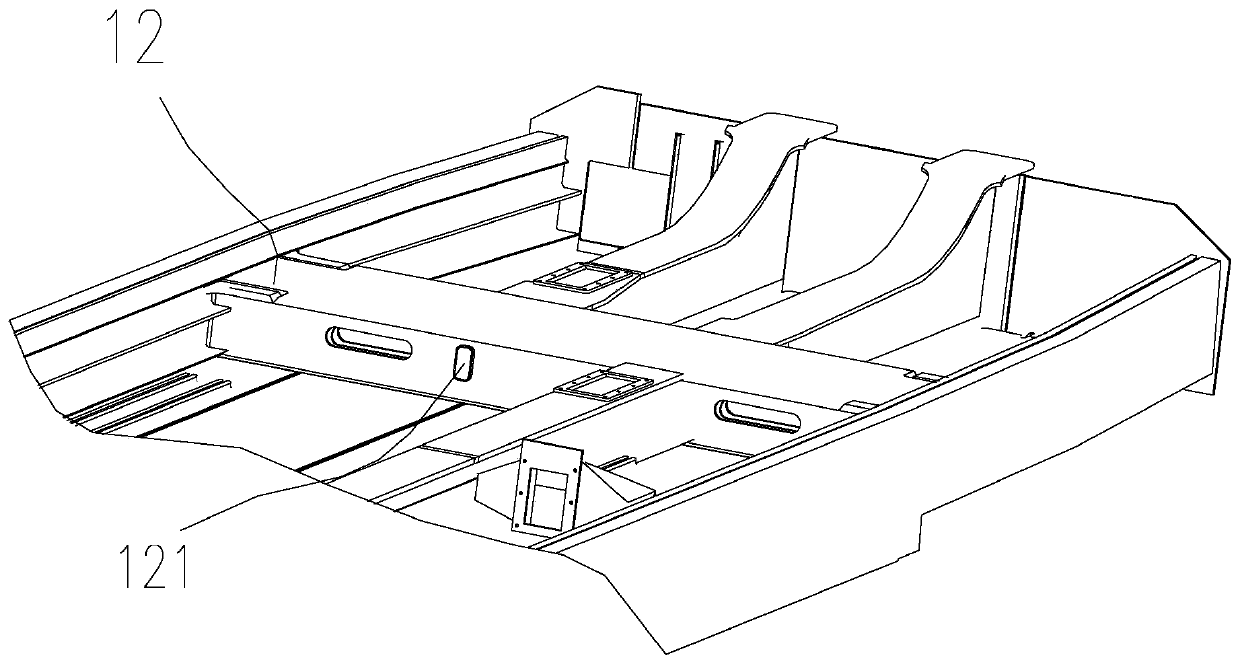
[0038] Such as Figure 1-Figure 7 As shown, the present invention discloses an underframe structure of a rail vehicle, which includes an underframe side beam 2, a floor 4 and an end beam 5 at one end, where the underframe structure is the middle compartment or head of a high-speed rail or EMU The underframe structure of the car compartment, specifically, the underframe structure includes underframe side beams 2 arranged in parallel and opposite to each oth...


PUM


Abstract

The invention discloses a railway vehicle and an underframe structure thereof. The chassis structure comprises underframe edge beams, a floor, an end beam, a first sleeper beam, and a second sleeper beam, wherein the underframe edge beams are parallelly and oppositely arranged, and the end beam are arranged at one end of the structure. The upper portion of the middle part of the underframe edge beams is provided with a middle door hole, and the lower portion of the middle part of the underframe edge beams is provided with a mounting cavity, wherein the mounting cavity is used for mounting mobile pedals. A stair reinforcing device comprises cross beams, a short longitudinal beam and a long longitudinal beam, wherein the cross beams are arranged on the two sides of the middle door hole and used for connecting the two oppositely-arranged underframe edge beams, and the upper portions of the cross beams are in plug-in connection with the floor. The short longitudinal beam is connected to the cross beams at two sides, the long longitudinal beam is connected with the first sleeper beam and the cross beam corresponding to one side of the first sleeper beam, and the distance from the firstsleeper beam to the cross beam corresponding to one side of the first sleeper beam is not greater than that from the second sleeper beam to the cross beam corresponding to one side of the second sleeper beam. According to the railway vehicle and the underframe structure thereof, due to the force transfer between the long longitudinal beam, the cross beams and the short longitudinal beam, the bearing capacity, especially anti-longitudinal impact capacity, of underframe edge beams at the portion of the middle door hole is improved, thus meeting collision requirements when accidental collision occurs between vehicles; in addition, the problem of insufficient strength and rigidity in a middle-arranged vehicle door and a stair rear underframe structure can be solved.

Description

technical field [0001] The invention relates to the technical field of rail vehicles, in particular to a rail vehicle and its underframe structure. Background technique [0002] With the development of society, people have higher and higher requirements for the safety of rail vehicles. [0003] As the trains run across the railway section, the platform heights in different regions are not the same. In order to facilitate passengers to get on and off the train, it is necessary to change the vehicle design to adapt to platforms of different heights. In order to adapt to platforms of different heights, a multi-level staircase structure needs to be set up in the door area. The staircase structure causes the side beams of the underframe to be nearly broken, the strength of the side beams drops sharply, and it is also a stress mutation point, especially for collisions, which are transmitted through the side beams. Due to the sudden reduction of the section of the side beam and th...

Claims


Application Information

Patent Timeline
IPC IPC(8): B61F5/50
CPCB61F5/50
Inventor 岳译新王赵华刘永强苏永章苏柯王海钧李涛
Owner ZHUZHOU ELECTRIC LOCOMOTIVE CO
Why Eureka
Try Eureka