Photographic processor

A film processor and photographic film technology, applied in the direction of mechanical transmission of exposure materials, liquid processing, photosensitive materials, instruments, etc., can solve the problems of low-efficiency use of processing liquid, damage to processing equipment, liquid overflow, etc.

Inactive Publication Date: 2003-03-12
EASTMAN KODAK CO
View PDF7 Cites 0 Cited by
  • Summary
  • Abstract
  • Description
  • Claims
  • Application Information

AI Technical Summary

Problems solved by technology

This vortex can actually cause the rinse part to dry out in the rinse tank
Too much flushing solution at one end of the tank and too little flushing solution at the other end, both of which can damage the flushing equipment
[0006] It can thus be seen that when a narrow flush tank is used in conjunction with an impingement nozzle for directing the flushing solution into the tank, inefficient use of the flushing solution may result because the temporary excess overflow from flush section
In addition, harmful eddy currents of the flushing solution may also create

Method used


Image

  • Photographic processor
  • Photographic processor
  • Photographic processor

Examples


Embodiment Construction

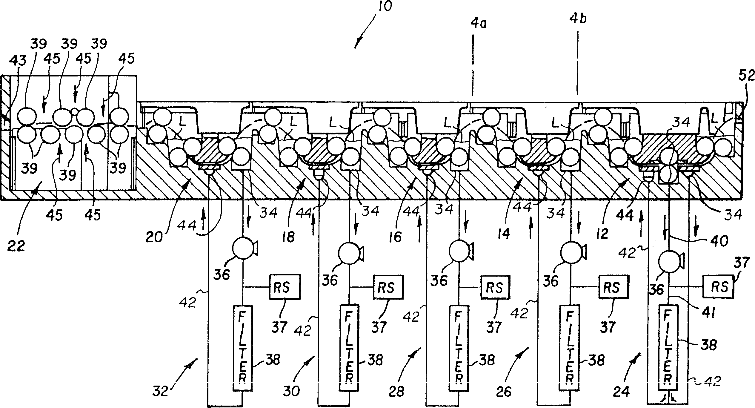
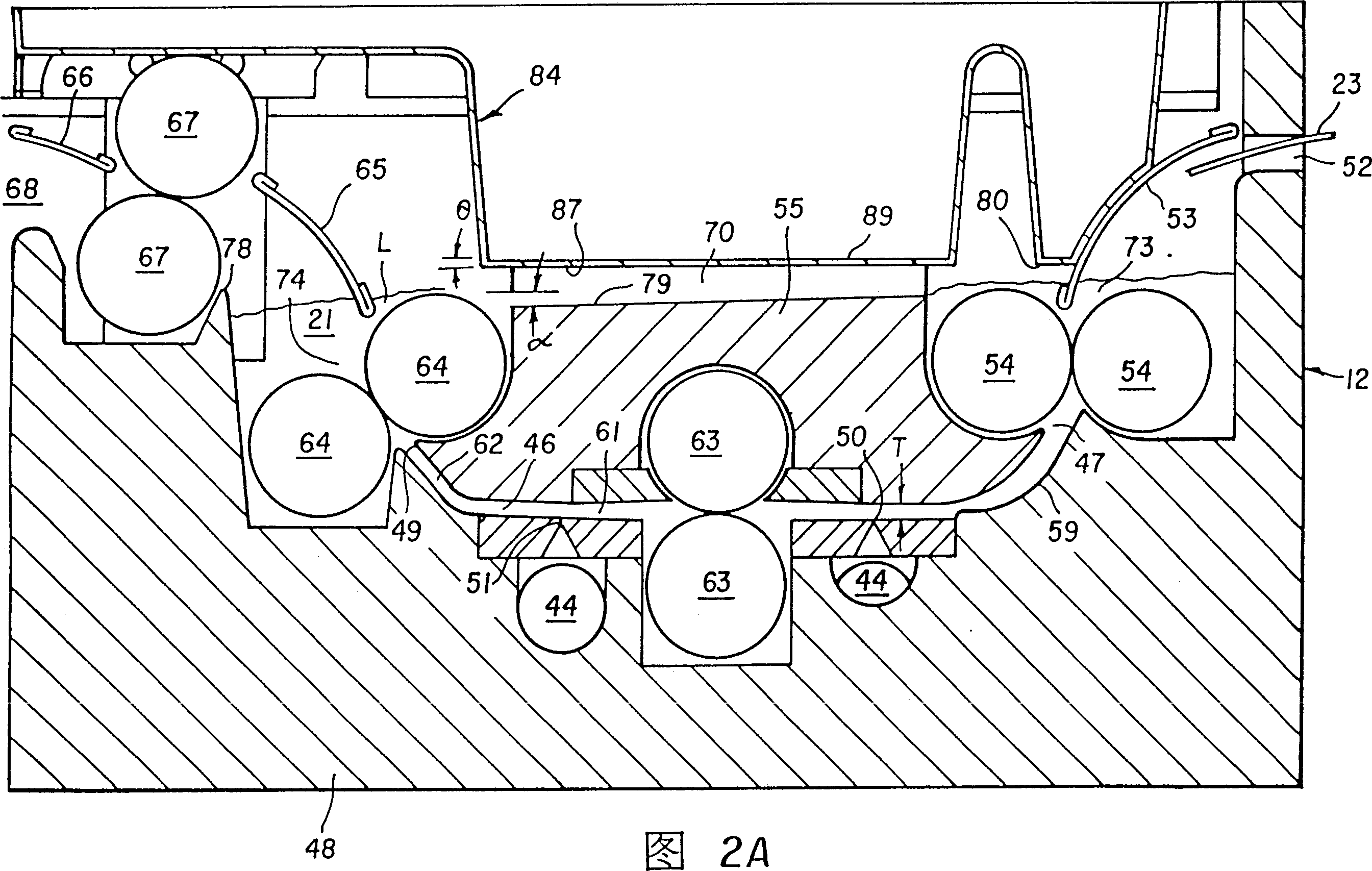
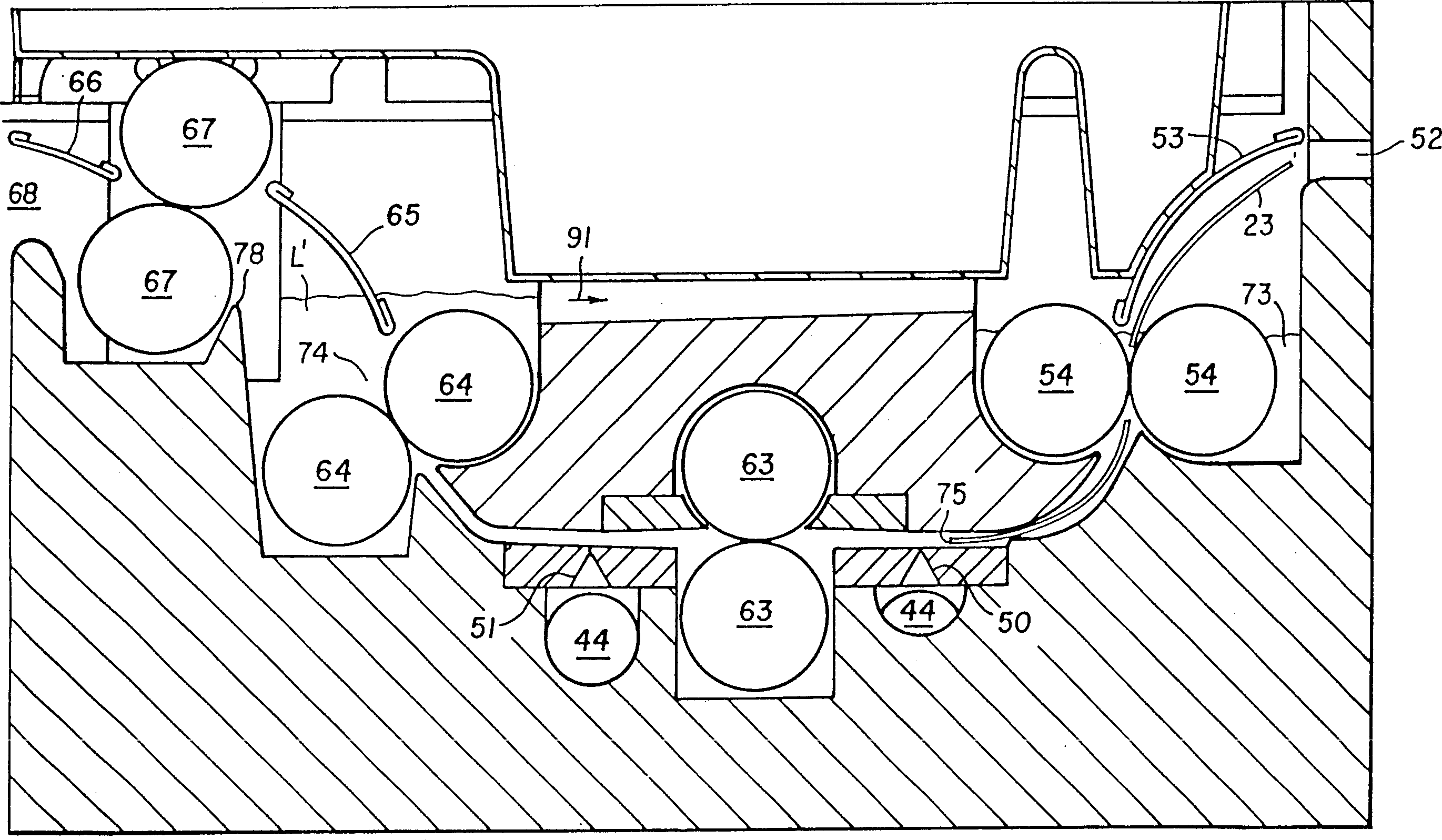
[0017] see figure 1 , shows a film processor 10 made according to the present invention. The film processor includes a plurality of processing sections 12, 14, 16, 18, 20, each processing section is used to hold a processing solution 21 for a photosensitive article 23 passing through the section (see Figure 2B ) for flushing. In the particular embodiment shown, processing section 12 contains a developing processing solution; processing section 14 contains a bleach-fix processing solution; and processing sections 16, 18, 20 each contain a stabilizing Agent flushing liquid. The liquid level of the rinsing liquid in each rinsing part is represented by the letter L. The dryer 22 is provided for drying the photosensitive article 23 after the photosensitive article 23 is discharged from the last processing section 20 .

[0018] Dryer 22 includes a plurality of rollers 39 for guiding and transporting photosensitive article 23 through dryer 22 . A suitable mechanism (which is we...


PUM


Abstract

An apparatus for processing a photosensitive material. The apparatus has a narrow processing channel for containing a processing solution for processing a photographic material. The processing channel has an inlet and an outlet. An entrance fluid retention area is provided adjacent the inlet and an exit fluid retention area is provided adjacent the outlet. A fluid balancing channel is provided which extends between said entrance fluid retention area and said exit fluid retention area.

Description

technical field [0001] The invention relates to the field of photographic film processors, in particular to a small-capacity elongated groove type film processor. Background technique [0002] US Patent Nos. 5270762; 5353088; 5400106; 5420659; 5313243; 5355190; 5398094; 5418591; 5347327; 5386261; . A nozzle is typically used to impinge a jet of processing solution on a photosensitive article as it passes through the processing tank. Processors of this type are also of low capacity construction in order to minimize the amount of processing solution present in the processing section. As a result of this type of construction, an inlet fluid stagnation zone is formed at the inlet end of the rinsing tank and an outlet fluid stagnation zone is formed at the outlet end of the rinsing tank. The liquid level of the flushing liquid in the two stagnation zones is substantially maintained by the fluid flowing through the flushing tank. [0003] Although this ty...

Claims


Application Information

Patent Timeline
Patent Type & Authority Patents(China)
IPC IPC(8): G03D3/02G03D3/06G03D3/13
CPCG03D3/132
Inventor J·H·罗森堡R·L·皮西尼诺
Owner EASTMAN KODAK CO
Why Eureka
Try Eureka