Actuator for a fan-powered damper

a technology of damper and actuator, which is applied in the direction of lighting and heating apparatus, heating types, ventilation systems, etc., can solve the problems of reducing the efficiency of the blade when fully open, inaccurate blade positioning, and increasing the cost of the blad

Active Publication Date: 2010-12-16
TRANE INT INC
View PDF44 Cites 14 Cited by
  • Summary
  • Abstract
  • Description
  • Claims
  • Application Information

AI Technical Summary

Benefits of technology

[0008]Another object of some embodiments is to provide a damper that under the impetus of a given air pressure differential can open to infinite select open positions.
[0010]Another object of some embodiments is allow an actuator to separate from a bar or blade-connecting member that interconnects a plurality of damper blades, whereby the damper blades can quickly move to a closed position without the actuator having to respond as quickly.
[0012]The present invention provides a damper for controlling air having an air pressure differential. The damper comprises a housing defining an opening across which the air pressure differential exists. A plurality of damper blades are pivotally mounted to the housing in proximity with the opening. The plurality of damper blades are movable over a range of pivotal positions between a more-open position and a less-open position. The air is more free to flow through the opening when the plurality of damper blades are in the more-open position than when the plurality of damper blades are in the less-open position. The air pressure differential urges the plurality of damper blades toward the more-open position. An abutment is coupled to the housing such that the abutment is movable relative to the housing and is movable relative to the plurality of damper blades. The abutment is movable over a range of blocking positions between a first position and a second position. The abutment in the first position holds the plurality of damper blades at the less-open position in opposition to the air pressure differential. The abutment in the second position allows the air to move the plurality of damper blades toward the more-open position.
[0013]The present invention also provides a damper for controlling air, wherein the damper comprises a housing defining an opening. The damper also comprises a plurality of damper blades pivotally mounted to the housing in proximity with the opening. The plurality of damper blades are movable over a range of pivotal positions between a more-open position and a less-open position, wherein the air is more free to flow through the opening when the plurality of damper blades are in the more-open position than when the plurality of damper blades are in the less-open position. The damper also comprises a fan selectively energized and de-energized such that the fan when energized urges the air to flow through the opening such that the air urges the plurality of damper blades to the more-open position. The damper further comprises an abutment being coupled to the housing such that the abutment is movable relative to the housing and is movable relative to the plurality of damper blades. The abutment is movable over a range of blocking positions between a first position and a second position, wherein the abutment in the first position holds the plurality of damper blades at the less-open position regardless of whether the fan is energized, and the abutment in the second position allows the air to move the plurality of damper blades toward the more-open position when the fan is energized.

Problems solved by technology

Increasing a blade's strength and stiffness, however, can increase the blade's cost.
Moreover, stronger, thicker blades can increase the damper's airflow resistance and thus reduce its efficiency when fully open.
A second problem pertains to a drive actuator having to drive or tilt the blades both clockwise and counterclockwise to selectively open and close the damper.
Reversing the torque direction can involve backlash or play between the actuator and the damper blades, which can cause inaccurate blade positioning.
Also, repeated torque reversal can cause fatigue that can weaken various parts of the damper.

Method used


Image

  • Actuator for a fan-powered damper
  • Actuator for a fan-powered damper
  • Actuator for a fan-powered damper

Examples


Embodiment Construction

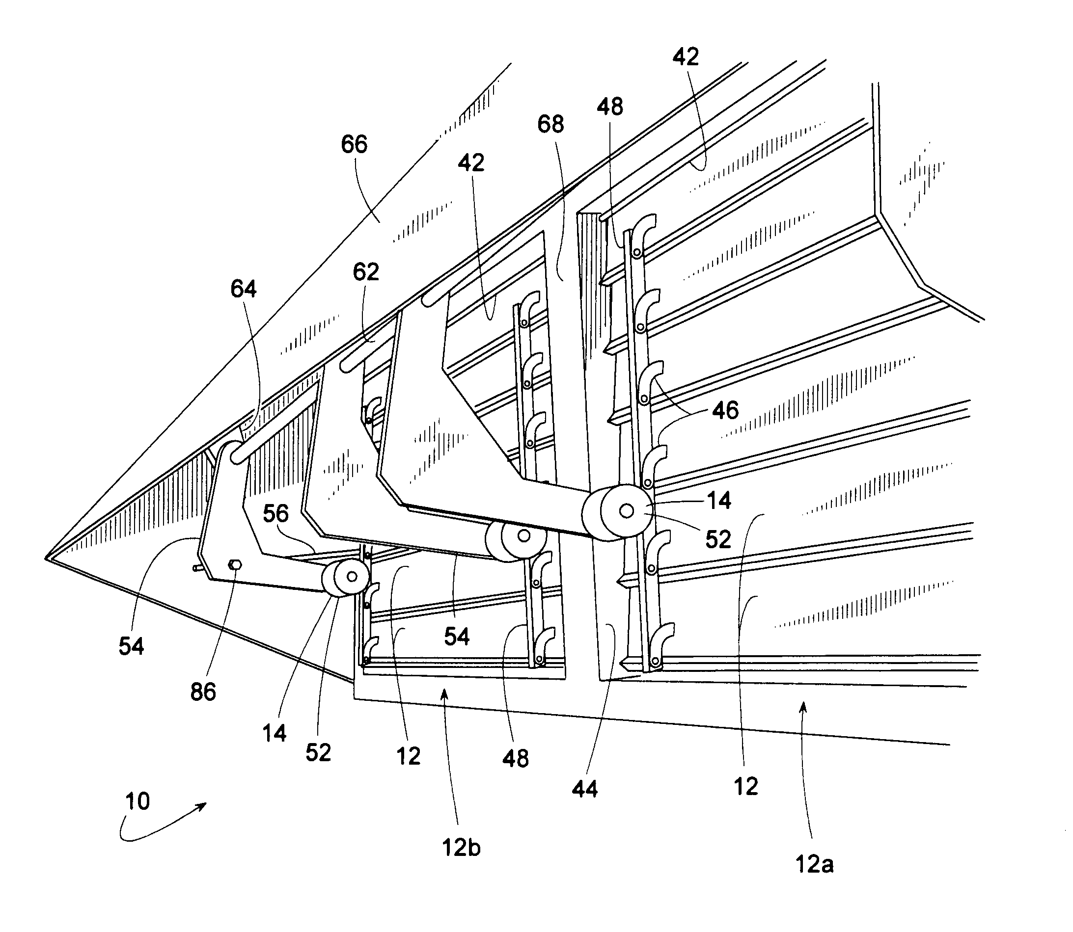
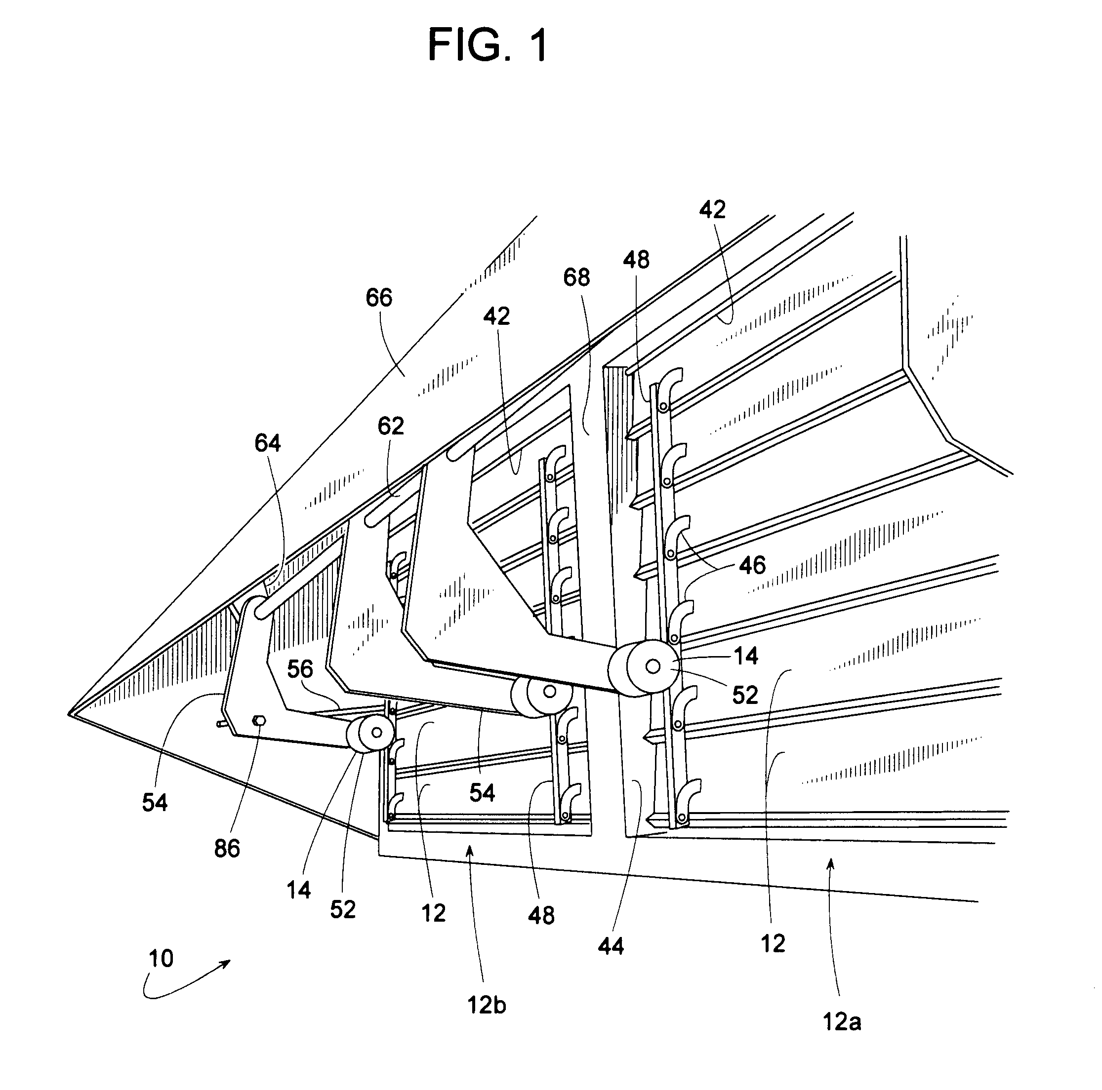
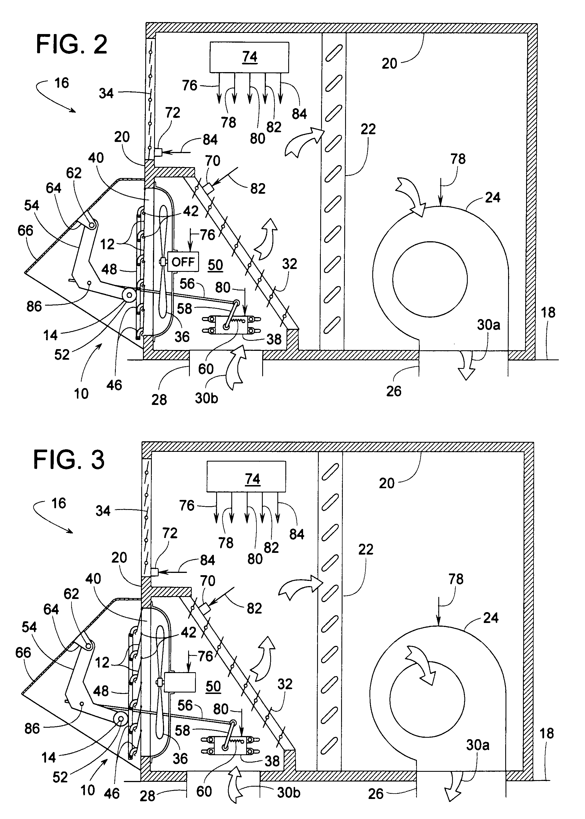
[0024]FIGS. 1-8 illustrate an air damper apparatus 10 that includes a plurality of damper blades 12 actuated by air pressure with the blades' pivotal travel being limited by a variable position abutment 14. Although damper 10 can be used in a wide variety of applications, damper 10 will be described, for sake of example, as being an exhaust damper for an HVAC air handler 16 such as those used for cooling or heating a comfort zone within a building 18.

[0025]In this example, air handler 16 comprises a housing 20 (e.g., a sheet metal enclosure), a heat exchanger 22 for heating or cooling air 30, a blower 24 for moving air 30, a supply air duct 26 for conveying conditioned air 30a to a comfort zone, a return air duct 28 for conveying used air 30b back to housing 20, a return air damper 32 for selectively directing air 30 either outside and / or to heat exchanger 22, a fresh air damper 34 for conveying outdoor air 30c into housing 20, exhaust air damper 10 for determining the amount of ret...


PUM


Abstract

An HVAC (heating, ventilating and air conditioning) damper includes a series of pivotal damper blades that are opened by an air pressure differential across opposite sides of the damper. In some embodiments, a fan discharging against the damper blades provides the necessary air pressure to open the damper. To control how far the damper opens, an actuator moves a variable position abutment that obstructs the damper blades to limit how far they can pivot in the open direction. The position of the abutment is infinitely adjustable to provide the damper with infinite adjustment over a range of open positions. In some embodiments, the abutment applies a unidirectional torque to the damper blades regardless of whether the damper is opening or closing.

Description

BACKGROUND OF THE INVENTION[0001]1. Field of the Invention[0002]The subject invention generally pertains to heating, ventilating and air conditioning (HVAC) dampers and more specifically to an actuator for such a damper.[0003]2. Description of Related Art[0004]HVAC systems often include various dampers for controlling airflow through the system. The dampers typically comprise a series of interconnected damper blades driven by an actuator that tilts the blades in unison between open and closed positions. A coupling or linkage that connects the drive actuator to the damper blades can transmit significant torque from the actuator to the blades, thus the blades need to be sufficiently strong to withstand such torque. Increasing a blade's strength and stiffness, however, can increase the blade's cost. Moreover, stronger, thicker blades can increase the damper's airflow resistance and thus reduce its efficiency when fully open.[0005]A second problem pertains to a drive actuator having to ...

Claims


Application Information

Patent Timeline
Patent Type & Authority Applications(United States)
IPC IPC(8): F16K13/00
CPCF16K1/165F24F13/1426F24F2013/1473
Inventor HILDRETH, JR., EDWARD DOUGLASSCHULT, ROBERT F.DUVVADA, GOUTAMGOODMAN, DOYLE R.HUSS, GARY A.STEPHANS, MARK W.
Owner TRANE INT INC
Why Eureka
Try Eureka