
Elevating exercise bicycle

a technology of exercise bicycle and inclination, which is applied in the field of fitness industries, can solve the problem that the type of exercise bicycle does not offer this kind of function

Inactive Publication Date: 2008-07-15
SOMWONG BANYAT
View PDF8 Cites 15 Cited by
  • Summary
  • Abstract
  • Description
  • Claims
  • Application Information

AI Technical Summary

Benefits of technology

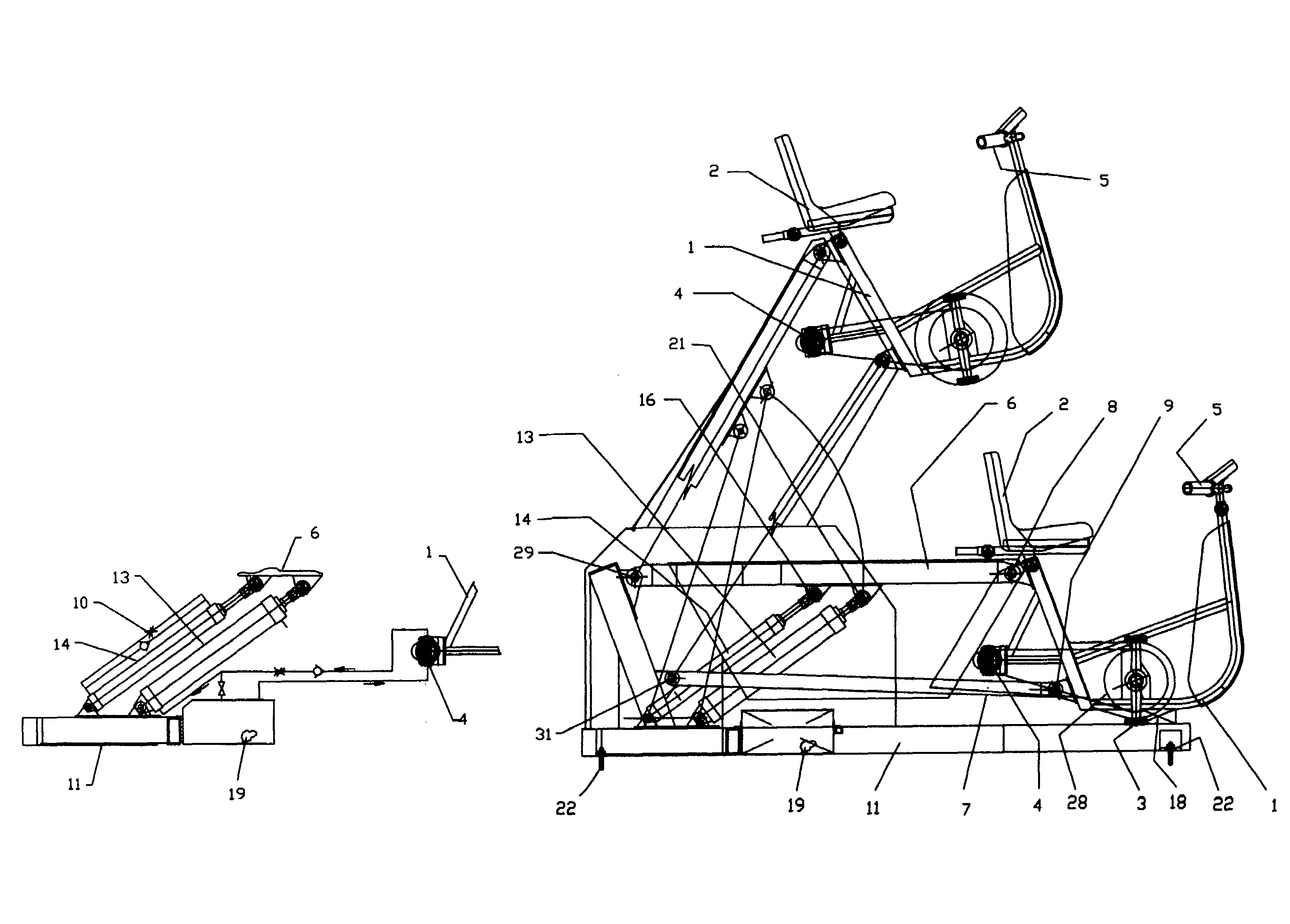
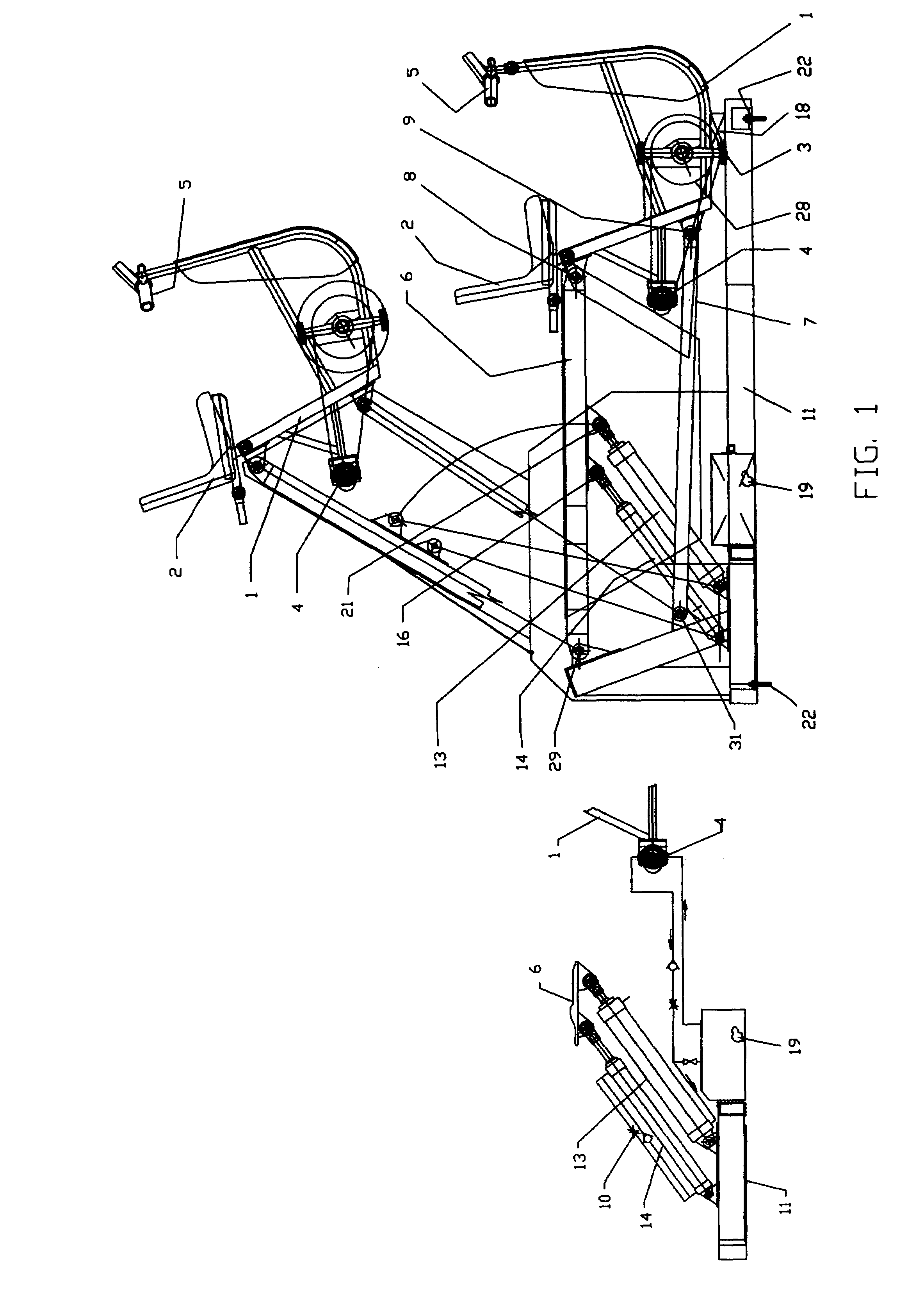
[0013]The purpose of the second actuator is to provide safety to the operator in case of main actuator failure caused by hydraulic lines are rupture. Two parallel lines connected between the lower port and upper port of the auxiliary actuator. One line furnished with check valve to prevent oil flow from lower port to upper port but free flow from top to the bottom. The other line is furnished with flow control valve to control flow rate in both directions. The purpose of this arrangement is to reduce the lowering speed in case of main actuator failure. The second actuator to be filled up with hydraulic oil prior to final installation. The lifting height as designed is about four feet from the home position. To lower the seat frame down to the home position, operator need to activate the pressure relief valve switch located on the instrument panel to drain oil from main actuator lower port back to the reservoir tank. The lowering speed is controlled by auxiliary actuator not to exceed predetermined set up.
[0014]To obtain the stability, rigidity and torsional stiffen of the bicycle frame, upper and lower arm are designed using A-frame principle and tubular member. The bicycle frame is also fabricated from structural tubing.

Problems solved by technology

The conventional type of exercise bicycle does not offer this kind of function which will attracts the occupant to spent longer time on the equipment for the sake of their health.

Method used


Image

  • Elevating exercise bicycle
  • Elevating exercise bicycle
  • Elevating exercise bicycle

Examples


Embodiment Construction

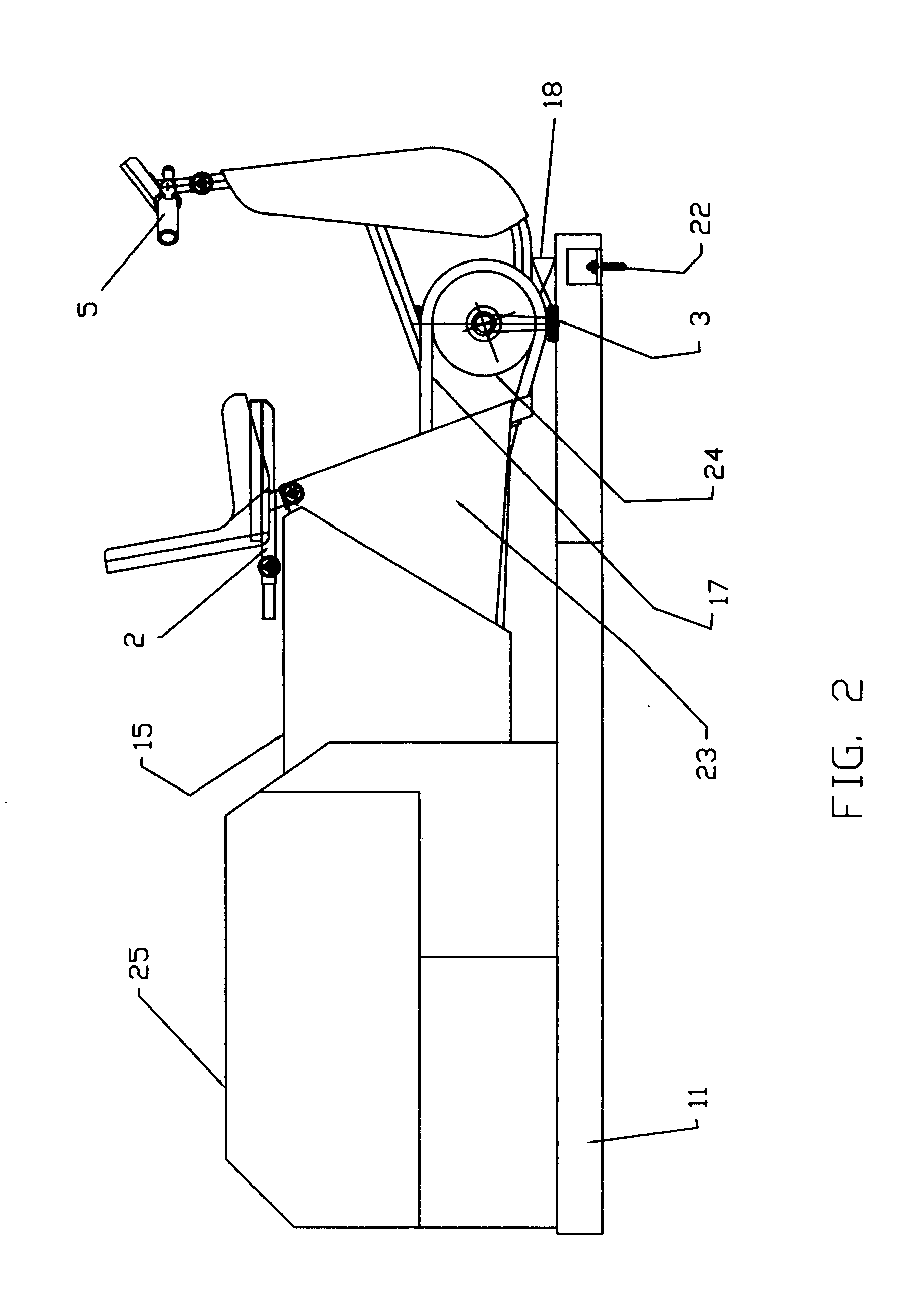
[0022]Referring to the drawings, FIG. 1 discloses the embodiment of the invention for a single seat Elevating Exercise Bicycle. The bicycle frame 1 includes a seat and seat adjustment members 2, a control and instrument panel 20, pedaling assembly 3, hydraulic pump 4, hydraulic cylinders 13, 14 and handle bar 5. The inclined vertical tubular member 1A of the bicycle frame that support seat assembly 2 is in turn supported by upper arm 6 and lower arm 7 via connecting pins 8,9 to allow angular movement of the frame 1 from a home rest position to a raised top position. Rear ends of the upper arm 6 and lower arm 7 are also attached to the base frame 11 through the connecting pins 29 and 31 respectively. The top mounting points 21, 16 of the two linear actuators are located substantially at the midpoint of the upper arm 6 and the bottom mounting points of the two linear actuators are located at the base frame member 11. The main actuator or cylinder 13 is controlled by flow control valve...


PUM


Abstract

An Elevating Exercise Bicycle for fitness and amusement ride in one having occupant-seating station with frame attached to a support base frame through an articulating member providing angular rotation about lower pivot pins to create constant pitching angle and vertical movement for occupant-seating station. Hydraulic pressure powered by occupant's energy via foot pedal and a drive chain to the pump increased the pressure inside the hydraulic system. Hydraulic pressure from the pump transferred to a main cylinder lower port, extending the piston rod and pushing an articulating member to move. Angular movement of the articulating member caused an occupant-seated frame to follow in ascending or descending motion depending on piston rod movement.Each cycle of workout for occupant can be preset to required load level.

Description

CROSS-REFERENCE TO RELATED APPLICATIONS[0001]“Not applicable”STATEMENT REGARDING FEDERALLY SPONSORED RESEARCH OR DEVELOPMENT[0002]“Not applicable”THE NAMES OF THE PARTIES TO A JOINT RESEARCH AGREEMENT[0003]“Not applicable”INCORPORATION-BY-REFERENCE OF MATERIAL SUBMITTED ON A COMPACT DISC[0004]“Not applicable”BACKGROUND OF THE INVENTION[0005](1) Field of the Invention[0006]The invention relates generally to the field of fitness industries which simulate exercise bicycle rides and amusement rides with ascending motion.[0007]In particular “Elevating Exercise Bicycle” provides for independent speed and resistance control of vertical motion on upward and predetermined down ward motion.[0008](2) Prior Art[0009]Existing exercise bicycles for workout and training are well known in the art. Conventional type bicycle simulators for use by the fitness industries and gym are stationary and simple. Elevating Exercise Bicycle offers movement of amusement ride and workout equipment in one. A typic...

Claims


Application Information

Patent Timeline
Patent Type & Authority Patents(United States)
IPC IPC(8): A63B22/06A63B21/00A63B21/068A63B22/08A63B69/16
CPCA63B22/0605A63B21/158A63B21/068
Inventor SOMWONG, BANYAT
Owner SOMWONG BANYAT
Learn More