
Protective face mask

Inactive Publication Date: 2008-03-20
KREAPS
View PDF11 Cites 12 Cited by
  • Summary
  • Abstract
  • Description
  • Claims
  • Application Information

AI Technical Summary

Benefits of technology

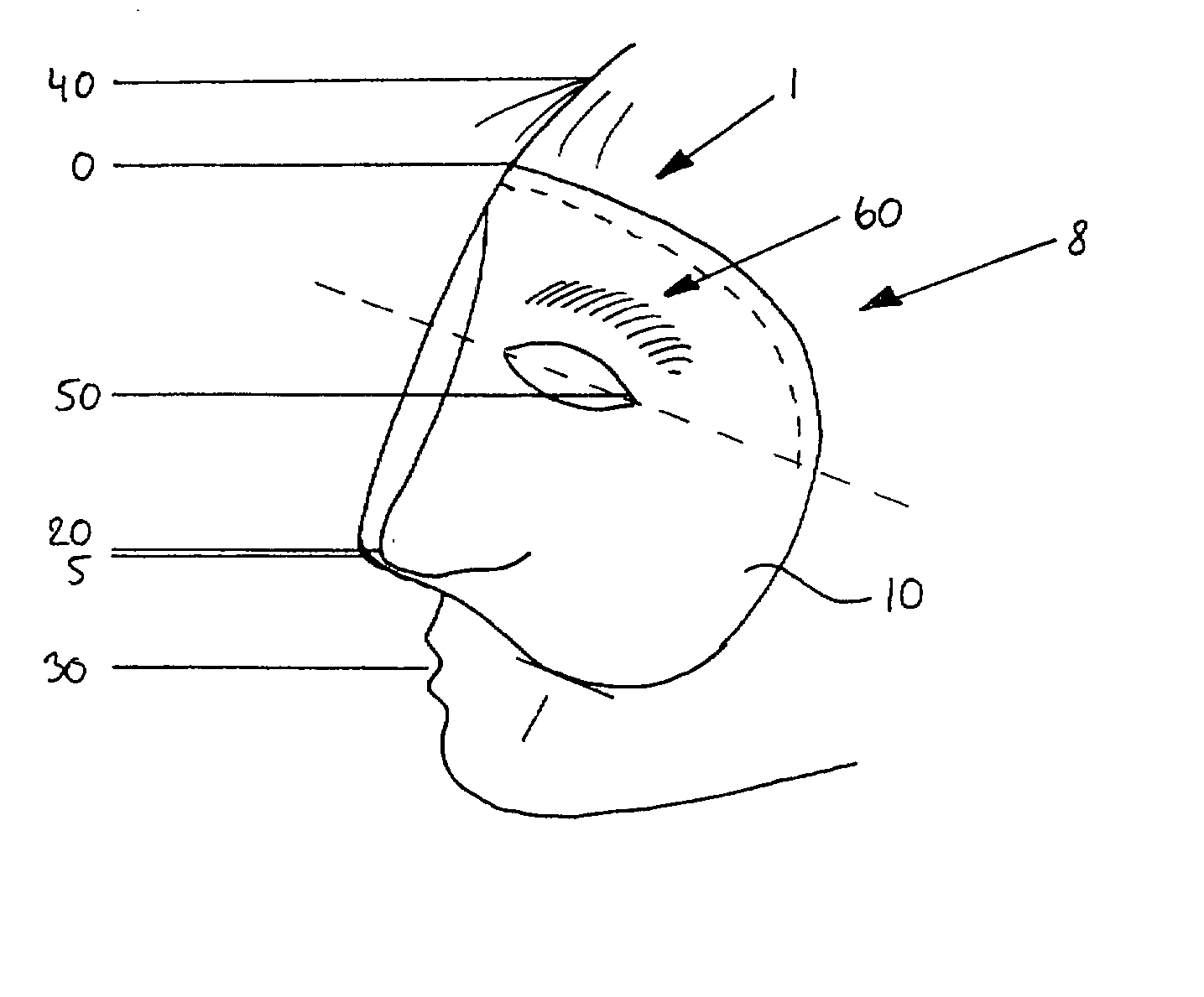
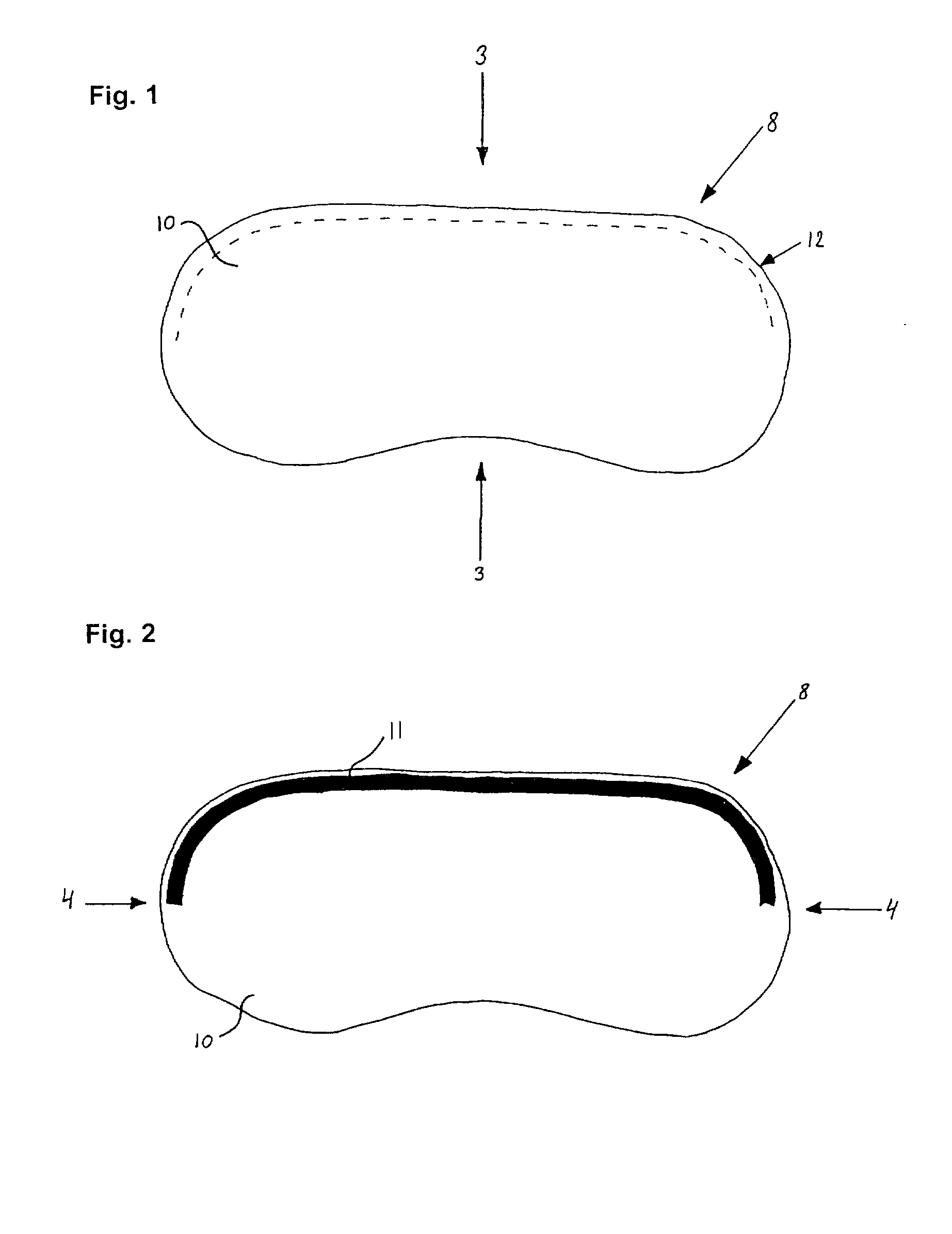
[0009] It is an object of preferred embodiments of the present invention to provide a comfortable, flexible face mask that provides a shield for the wearer's eyes without the need for straps, elastic bands or side bars for keeping the face mask in place, said face mask being comfortable and easy to use.
[0010] It is a further object of preferred embodiments of the present invention to provide a face mask, which avoids pressure on the skin in the contact zone between seal and skin, and which allows free eye movement.
[0011] Still further it is an object of the invention to provide a face mask which allows for free airflow to the eye region and nose and mouth allowing free breathing through the nose and the mouth, and which minimizes the inconvenience of dewing on the surfaces of the mask and leaves the jaw area free enabling unhindered jaw movement, e.g. when speaking.

Problems solved by technology

The sealing can cause pressure on the skin in the contact zone between the seal and the skin, thereby causing restrictions on eye contour movements.
The sealing may further cause pressure marks on the skin.
As the shield disclosed in U.S. Pat. No. 4,856,535 extends beyond the chin of the patient humidity from exhaled air will condense at the inner surface thereof and form dew being highly undesirable, especially if used for protecting children's eyes, nose and mouth during bathing.
Furthermore, children may feel isolated behind a full face mask covered with dew.

Method used


Image

  • Protective face mask
  • Protective face mask
  • Protective face mask

Examples


example

Comparison of Flow of Water from Face Protection Masks Having Differently Shaped Bottom Edges.

[0112] Shields made from PU sheet and specimen having a bottom edge having one central convex part, having a bottom edge having a convex-concave-convex shape, having a linear horizontal bottom edge and having one convex bottom part offset the centre were tested.

[0113] For each specimen water was sprayed onto the shield using a shower and the pattern of draining off of water was noted. The results are presented in FIGS. 18-21.

[0114] The result from testing the specimen having bottom edge having one central convex part appears from FIG. 18 showing that when the water streams 120 hit the face mask 8, water streams towards the tip 5 of the convex bottom edge 6, creating a draining of water from the tip 5 over the nose and mouth region.

[0115] The result from testing the specimen having a bottom edge having convex-concave-convex shape appears from FIG. 19 showing that when the water streams ...


PUM


Abstract

A protective face mask comprising: an eye-protecting shield made essentially from a plastics material, the eye-protecting shield being dimensioned to cover at least the eye portions of a human wearer, the eye-protecting shield having a perimeter defining a first surface facing the wearer's face, and a second surface facing away from the wearer's face; an adhesive forming an adhesive strip attached to the first surface of the eye-protecting shield for providing a substantially watertight and releasable sealing engagement between at least a portion of the perimeter forming an upper edge of the face mask and at least a portion of the skin of the wearer's face, wherein the upper part of the perimeter of the mask is provided with a continuous layer of adhesive along the perimeter, and the lower part of the perimeter of the mask is free of adhesive, the lower part of the perimeter forms a bottom edge of the mask being provided with at least one part forming a projection offset from the centre line of the mask, and wherein the mask extends along the contour of the wearer's face from the forehead to cheekbones and the lower perimeter thereof extends above the mouth provides a comfortable and flexible mask without the need for straps, elastic bands or side bars, avoids pressure on the skin in the contact zone, allows free eye movement and airflow and minimizes the formation of dew.

Description

[0001] The present invention relates to a face mask comprising a protective eye shield dimensioned to cover at least the eye portions of a human wearer. The face mask is particularly useful for shielding against water or shampoo during showering and hair washing. The face mask is also applicable in hairdressing for protecting the wearer's eyes from hair tonic, rinse, hair spray, hair colour and clippings, or in the area of leisure, e.g. for protecting bikers', runners' or hikers' eyes from rain, wind, sun and bugs. BACKGROUND OF THE INVENTION [0002] 1. Field of the Invention [0003] Eye goggles and face masks are habitually used to keep the wearer's eyes protected from external environments. For example, swimming goggles are used to protect the wearer's eyes from water. [0004] 2. Description of the Related Art [0005] Traditional eye goggles and face masks normally comprise a spongy or rubber-like material for providing a seal between a perimeter of the goggles or face masks and a por...

Claims


Application Information

Patent Timeline
IPC IPC(8): A61F9/00A41D13/00
CPCA61F9/04A45D44/12G02C5/008A41D19/00
Inventor KAYEROD, HELLE
Owner KREAPS
Learn More