
Blade torsional vibration displacement measurement method based on blade tip timing principle

A technology of torsional vibration and blade tip timing, applied in measuring devices, measuring ultrasonic/sonic/infrasonic waves, instruments, etc., can solve problems such as difficult sensor layout, no reports, and few research methods

Pending Publication Date: 2019-10-11
TIANJIN UNIV
View PDF0 Cites 11 Cited by
  • Summary
  • Abstract
  • Description
  • Claims
  • Application Information

AI Technical Summary

Problems solved by technology

Existing tip timing measurement methods, including speed vector end trace method [1] , two-parameter method [2] , autoregressive method [3] and sensor-based arbitrary angular distribution method [4] etc., only one blade tip timing sensor is installed at the same circumferential position of the rotary machine case, so it can only measure the bending vibration displacement of the blade, but cannot realize the measurement of the torsional vibration displacement of the blade
[0006] On the other hand, the mode shapes of the high-order vibration of the blade include bending vibration, torsional vibration, and combined bending-torsion vibration. The blade cracks or corner failures caused by torsional vibration often occur, but because the high-order vibration of the blade has an amplitude Due to measurement problems such as small size, complex mode shape, and difficult sensor layout, there are few researches on the measurement methods of blade high-order vibration parameters at home and abroad, especially for the measurement methods of blade torsional vibration displacement and other parameters.

Method used


Image

  • Blade torsional vibration displacement measurement method based on blade tip timing principle
  • Blade torsional vibration displacement measurement method based on blade tip timing principle
  • Blade torsional vibration displacement measurement method based on blade tip timing principle

Examples


Embodiment Construction

[0034] The following detailed description of the steps of manufacturing and operating the present invention is intended to be described as an embodiment of the present invention, and is not the only form that can be manufactured or utilized. Other embodiments that can achieve the same function should also be included within the scope of the present invention .

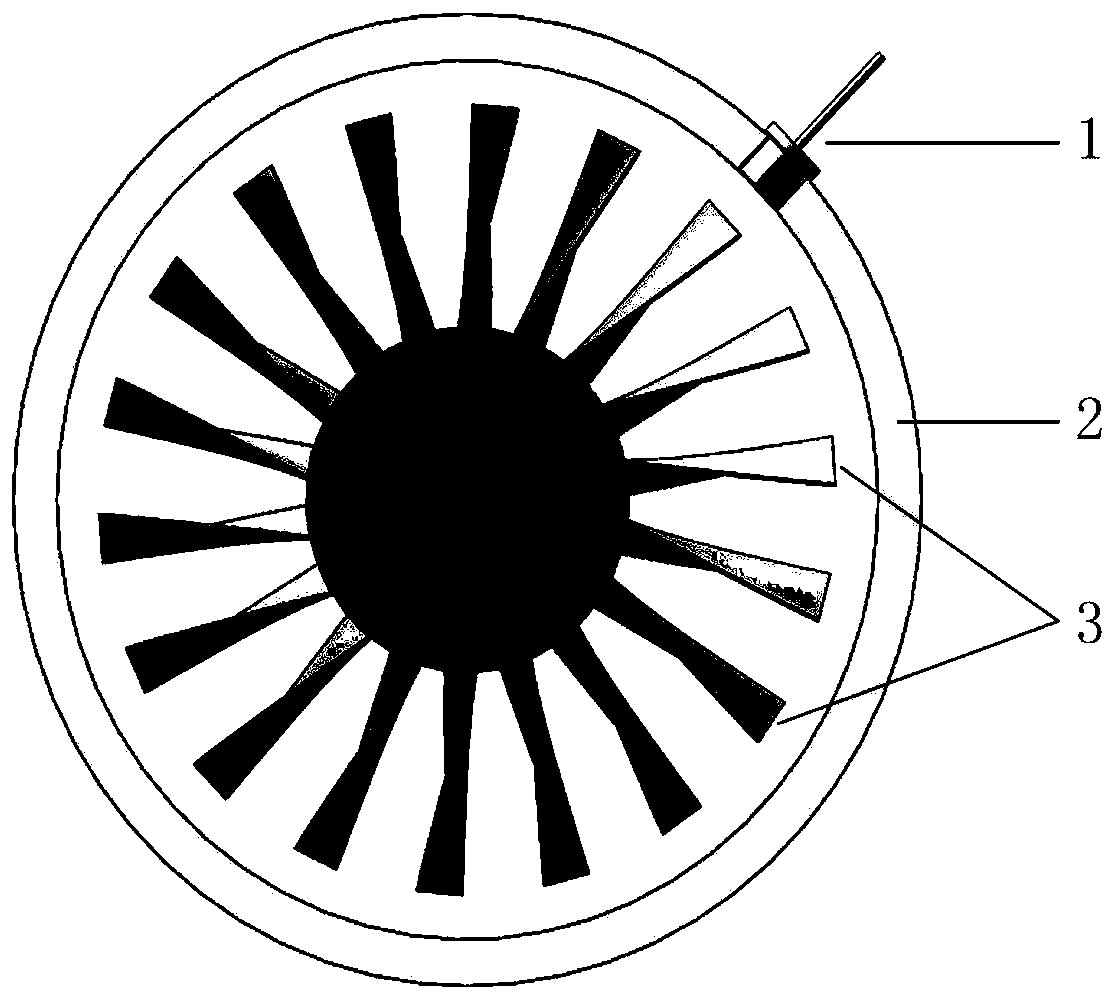
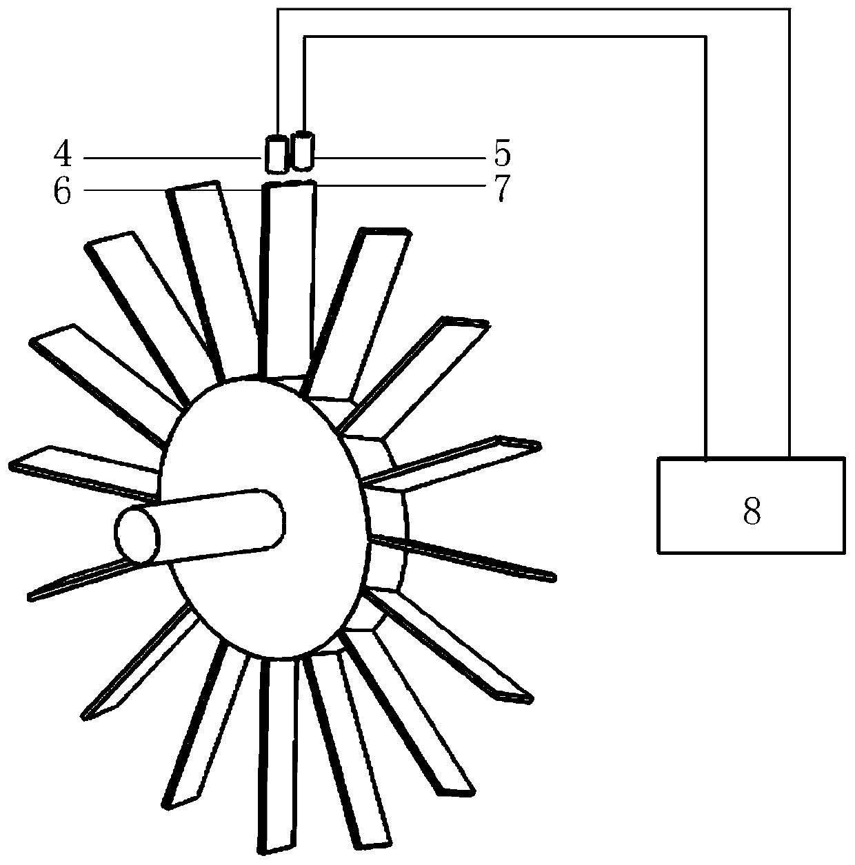
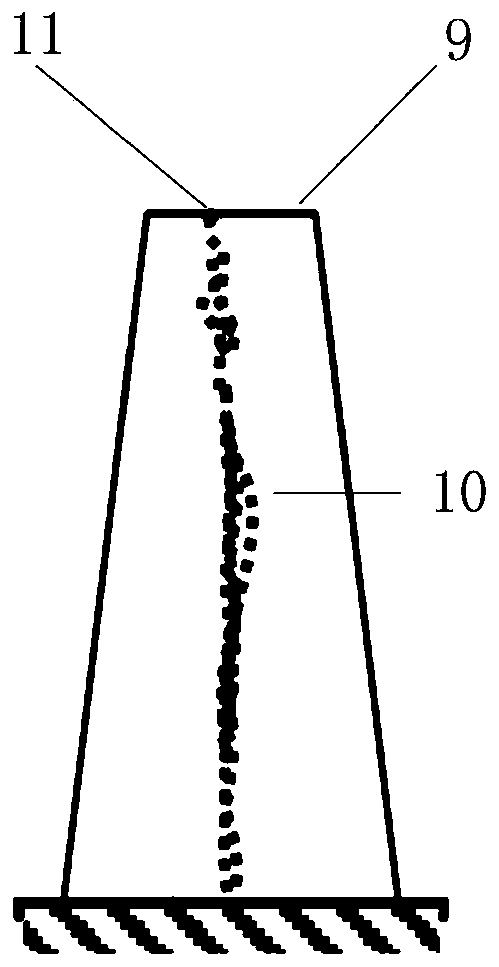
[0035] In the present invention, the top of the blade is called the blade end, the circumferential direction of the rotating mechanical casing is called the circumferential direction, the side of the blade facing the airflow direction is called the air inlet side, and the side of the blade facing away from the airflow direction is called the air outlet side. During torsional vibration, the circumferential distance difference generated by the edge of the blade end passing through the two blade tip timing sensors at the inlet side and the outlet side in the same circle is called the blade torsional vibration displacement....


PUM


Abstract

The invention relates to a blade torsional vibration displacement measurement method based on a blade tip timing principle. At the same circumferential position on a case of a rotary machine, two blade tip timing sensors in one group are arranged along the axial direction of a rotor, respectively called as an air inlet side blade tip timing sensor and an air outlet side blade tip timing sensor andused for measuring time of arriving at the blade tip timing sensors by an air inlet side and an air outlet side at the blade tip of the same blade in the same circle; the two blade tip timing sensorsare arranged at a projection point of a maximum displacement position of a torsional resonance blade tip on a blade tip rest position horizontal line, which is called as a torsional resonance projection process, and by combining torsional resonance parameters of the blade, optimal location of the blade tip timing sensors is realized by utilizing the torsional resonance projection process, so as to guarantee that the two blade tip timing sensors can sample a blade tip arrival time signal respectively and accurately under the condition that torsional resonance and torsional non-resonance of theblade occur; and blade torsional vibration displacement measurement is realized.

Description

technical field [0001] The invention belongs to the field of state monitoring of rotating machinery, in particular to a blade torsional vibration displacement measurement method based on the blade tip timing principle. [0002] technical background [0003] Important rotating machinery such as aero engines and steam turbines are the core components of key equipment such as military aircraft, commercial aircraft, generator sets and steam units in the aerospace and industrial fields. In particular, as the core component of rotating machinery, the working state of the moving blade directly affects the working efficiency, safety, stability, and long-term operation of these major key equipment. At present, the vibration measurement technology of rotating blades based on the principle of blade tip timing is a typical non-contact measurement method. The identification algorithm realizes the measurement of blade vibration parameters such as vibration amplitude, vibration frequency a...

Claims


Application Information

Patent Timeline
IPC IPC(8): G01H17/00
CPCG01H17/00
Inventor 段发阶邓震宇傅骁牛广越刘志博程仲海
Owner TIANJIN UNIV
Learn More