Printed board group

A technology of printed boards and elastic contacts, which is applied in the direction of contact parts, electrical components, coupling devices, etc., can solve the problems of high connection cost and poor flow capacity of printed boards, and achieve low cost, few components and easy installation. convenient effect

Inactive Publication Date: 2019-10-11
CHINA AVIATION OPTICAL-ELECTRICAL TECH CO LTD
View PDF6 Cites 1 Cited by
  • Summary
  • Abstract
  • Description
  • Claims
  • Application Information

AI Technical Summary

Problems solved by technology

[0005] The purpose of the present invention is to provide a printed board assembly to solve the problems of high connection cost and poor flow capacity of printed boards

Method used


Image

  • Printed board group
  • Printed board group
  • Printed board group

Examples


Embodiment Construction

[0019] Embodiments of the present invention will be further described below in conjunction with the accompanying drawings.

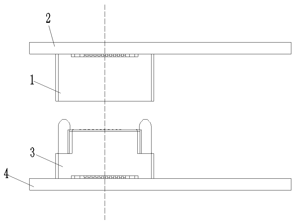
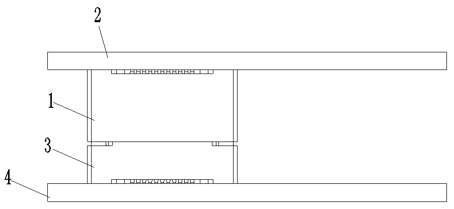
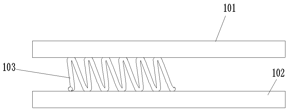
[0020] Example 1 of the printed board set, as Figure 3-4 As shown, in this embodiment, the printed board group has two printed boards, the two printed boards are parallel to each other and relatively fixed, the specific fixing method can be fixed by fasteners such as screws, or can be fixed by using The way of being stuck in the same housing is fixed, only need to realize the relative fixing of the two, and it is not necessary to list them one by one here. For ease of distinction, here image 3 The upper printed board is called the first board 101 , and the other printed board is called the second board 102 .

[0021] The first plate 101 and the second plate 102 are electrically connected through the elastic contact piece 103. The elastic contact piece 103 adopts a coil spring, and two conductive contact parts 21 are arranged on the outer peripheral s...


PUM


Abstract

The invention relates to the field of electric connectors, in particular to a printed board group. The printed board group comprises more than two printed boards which are relatively fixed, and elastic contact pieces which are electrically connected with the printed boards, wherein each elastic contact piece comprises one section or more than two sections of spiral springs which are arranged sideby side in the axial direction; each printed board is arranged around the elastic contact piece; the elastic contact pieces are pressed between the printed boards; and conductive contact parts which are in conductive contact with the printed boards are arranged on the outer peripheral surfaces of the elastic contact pieces. Compared with the electric connector adopted in the prior art, the inter-plate contact device has the advantages of the obviously fewer components, the simpler structure, the more convenient installation and the lower cost. In addition, because the spiral springs are adopted to be in contact conduction with the printed boards, at least two conductive structures can be formed in each circle, and compared with a one-to-one contact, more contacts can be provided in the same space, so that sufficient current capacity can be ensured.

Description

technical field [0001] The invention relates to the field of electrical connectors, in particular to a printed board assembly. Background technique [0002] With the rapid development of miniaturization and modularization of various electrical equipment and electronic equipment, printed board products with specific functions continue to increase. At present, it is often encountered that two printed board components are electrically connected to each other. [0003] In the prior art, in order to realize the electrical connection between two printed boards, a male connector is fixed on one of the two printed boards, and a female connector is fixed on the other. figure 1 It shows the separation state of the first printed board 2 with the female connector 1 installed and the second printed board 4 with the male connector 3 installed, figure 2 It shows the connection between the above-mentioned first printed board 2 and the second printed board 4 , that is, the plugged state of...

Claims


Application Information

Patent Timeline
IPC IPC(8): H01R13/24H01R12/71
CPCH01R12/71H01R13/2421
Inventor 刘向阳张智宇
Owner CHINA AVIATION OPTICAL-ELECTRICAL TECH CO LTD
Why Eureka
Try Eureka