Oral implant positioning drill bit

A drill bit and oral cavity technology, which is applied in the field of oral implant positioning drill bits, can solve problems such as unfavorable practical operation, easy drilling too deep, and inconvenient adjustment of the drill bit position

Inactive Publication Date: 2022-05-27
山东秦飞智能科技发展有限公司
View PDF4 Cites 0 Cited by
  • Summary
  • Abstract
  • Description
  • Claims
  • Application Information

AI Technical Summary

Problems solved by technology

[0004] In the actual operation of the existing positioning drill bit for oral implantation, it is extremely inconvenient to adjust the position of the drill bit, which is not conducive to the actual operation. damage to the nerve of the tooth

Method used


Image

  • Oral implant positioning drill bit
  • Oral implant positioning drill bit
  • Oral implant positioning drill bit

Examples


Embodiment 1

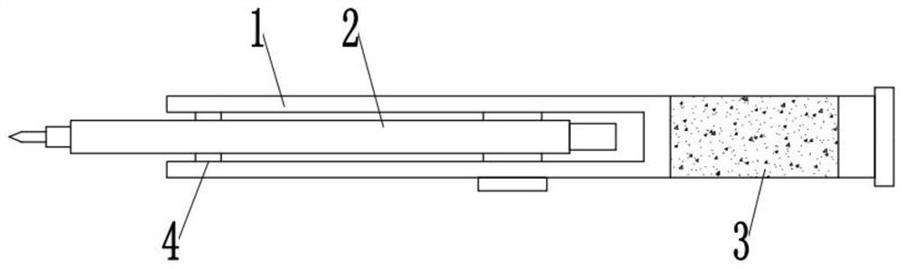
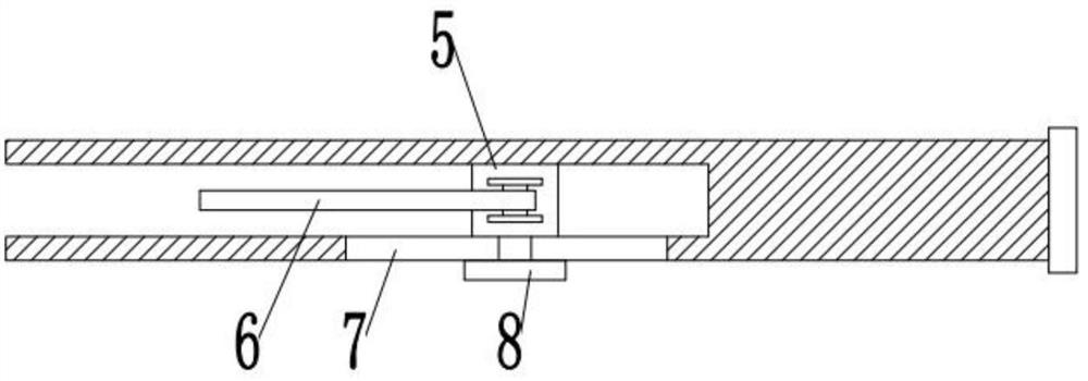
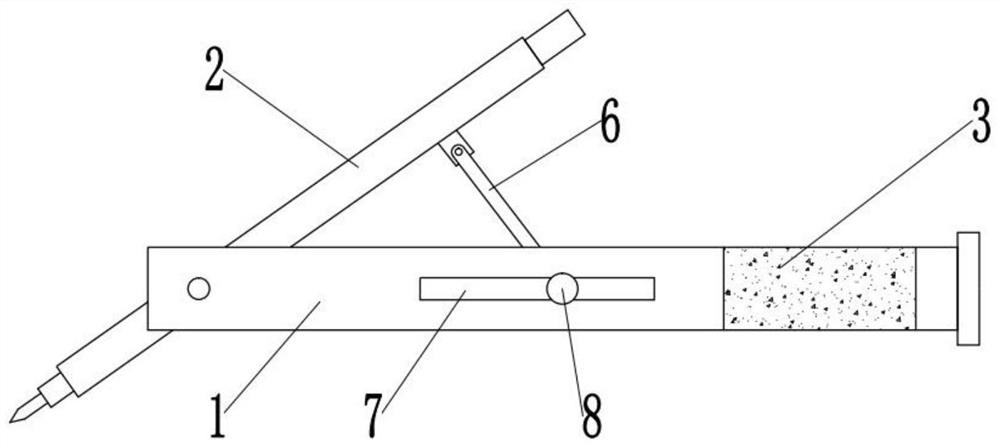
[0030] see Figures 1 to 4 , In the embodiment of the present invention, an oral implant positioning drill includes a frame 1 and a drilling mechanism 2; the frame 1 is a U-shaped structure, and the rear end of the frame 1 is provided with a holding part, The open end is provided with the drilling mechanism 2, and the drilling mechanism 2 is rotated on the frame 1 through the rotating shaft 4; the interior of the frame 1 is slidably installed with a sliding block 5, and the sliding block 5 is rotatably installed at one end of the push-pull rod 6 , the bottom of the drilling mechanism 2 is fixedly installed with a hinged seat, and the other end of the push-pull rod 6 is hingedly installed on the hinged seat. During the sliding process of the slider 5 inside the frame 1, the drilling mechanism is driven by the push-pull rod 6 2. Rotate to adjust the position of the drilling mechanism 2, so that the drilling mechanism 2 is precisely aligned with the teeth to be drilled;

[0031]...

Embodiment 2

[0036] see Figures 1 to 4 , In the embodiment of the present invention, an oral implant positioning drill includes a frame 1 and a drilling mechanism 2; the frame 1 is a U-shaped structure, and the rear end of the frame 1 is provided with a holding part, The open end is provided with the drilling mechanism 2, and the drilling mechanism 2 is rotated on the frame 1 through the rotating shaft 4; the interior of the frame 1 is slidably installed with a sliding block 5, and the sliding block 5 is rotatably installed at one end of the push-pull rod 6 , the bottom of the drilling mechanism 2 is fixedly installed with a hinged seat, and the other end of the push-pull rod 6 is hingedly installed on the hinged seat. During the sliding process of the slider 5 inside the frame 1, the drilling mechanism is driven by the push-pull rod 6 2. Rotate to adjust the position of the drilling mechanism 2, so that the drilling mechanism 2 is precisely aligned with the teeth to be drilled;

[0037]...


PUM


Abstract

The invention relates to the technical field of dental treatment, in particular to a dental implant positioning drill, comprising a frame and a drilling mechanism; the frame is a U-shaped structure, the tail end of the frame is provided with a gripping part, and the The drilling mechanism is provided, and the drilling mechanism is installed on the frame through the rotation of the rotating shaft; a slide block is slidably installed inside the frame, and a push-pull rod is installed on the slide block, and the bottom of the drilling mechanism is fixedly installed with a Hinged seat, the other end of the push-pull rod is hingedly installed on the hinged seat; the inside of the frame is provided with a chute, the inside of the chute is rotated with a screw rod, and the inside of the chute is also slidably installed with a slide bar, one end of the slide bar It is threadedly connected with the screw rod, and the other end of the slide rod is rotatably installed with a drill bit body. The invention drives the drilling mechanism to rotate through the push-pull rod, thereby adjusting the position of the drilling mechanism, so that the drilling mechanism can accurately align the teeth to be drilled, thereby effectively drilling the teeth.

Description

technical field [0001] The invention relates to the technical field of oral treatment, in particular to a positioning drill for oral implantation. Background technique [0002] The oral cavity refers to the cavity in the mouth, which is the initial part of the digestive tract. It consists of two lips, two cheeks, hard palate, soft palate, etc. There are teeth, tongue, salivary glands and other organs in the oral cavity. The anterior wall of the oral cavity is the lip, the lateral wall is the cheek, the roof is the palate, and the floor of the oral cavity is the mucosa and muscles. The oral cavity is divided into the oral vestibule in the anterolateral part and the proper oral cavity in the posteromedial part by the upper and lower dental arches. When the upper and lower jaw teeth are occluded, the oral vestibule and the proper oral cavity can be connected by the space behind the third molar. [0003] Teeth are a structure that exists in many vertebrates. Generally speaking,...

Claims


Application Information

Patent Timeline
Patent Type & Authority Patents(China)
IPC IPC(8): A61C8/00A61C8/02
CPCA61C8/00A61C8/0089A61C8/0004A61C8/0009
Inventor 齐立东冯涛谢翼
Owner 山东秦飞智能科技发展有限公司
Why Eureka
Try Eureka