Building wall groove digging device

A technology for building walls and planing and digging, which is applied in construction, sheet pile walls, earth movers/excavators, etc., and can solve problems such as cumbersome work processes

Inactive Publication Date: 2019-09-20
安徽天驰建工集团有限公司
View PDF5 Cites 3 Cited by
  • Summary
  • Abstract
  • Description
  • Claims
  • Application Information

AI Technical Summary

Problems solved by technology

However, this device needs to discharge the waste soil generated during the trough forming process from the upper end, and the working process is cumbersome

Method used


Image

  • Building wall groove digging device
  • Building wall groove digging device
  • Building wall groove digging device

Examples


specific Embodiment approach 1

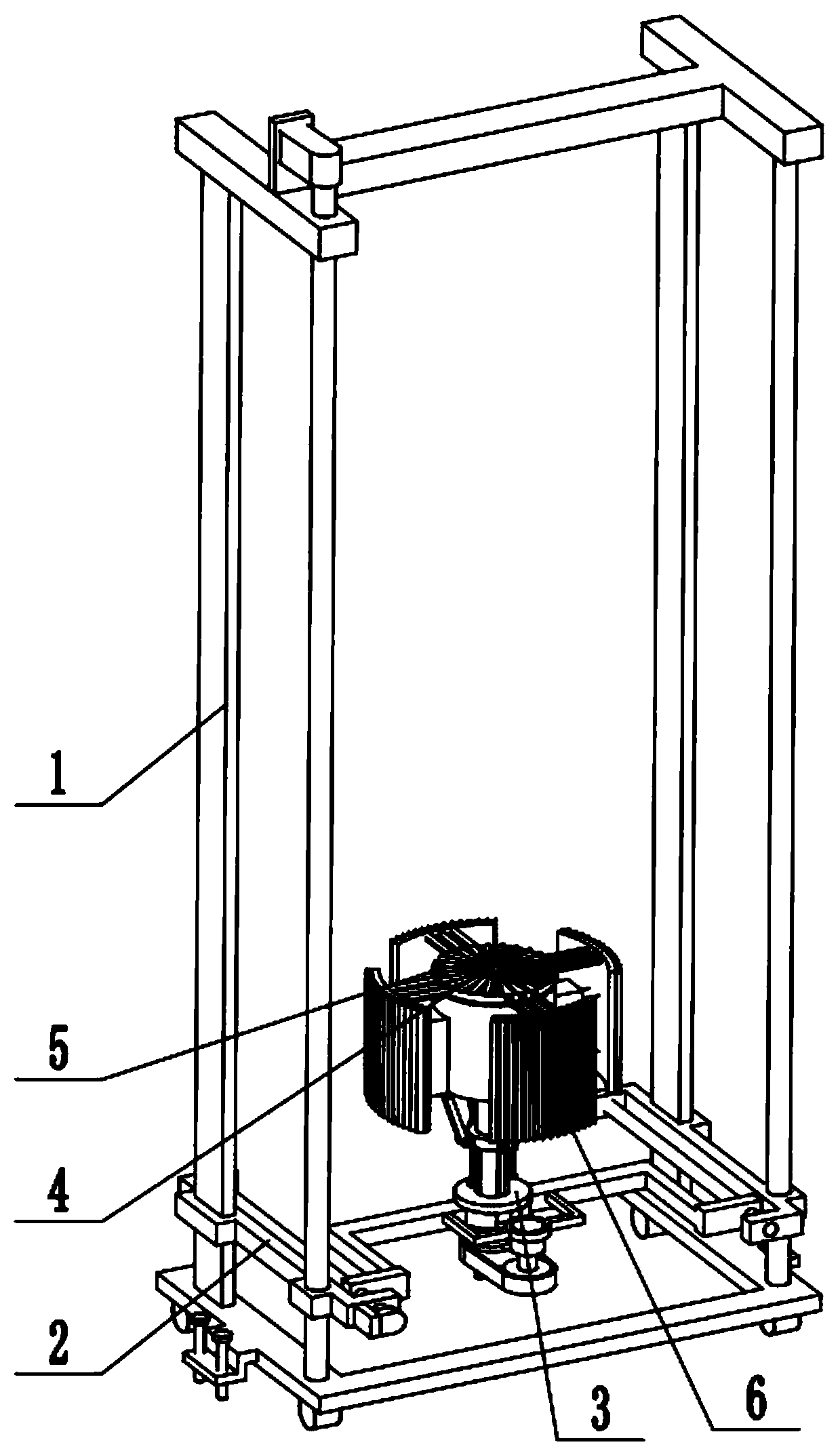
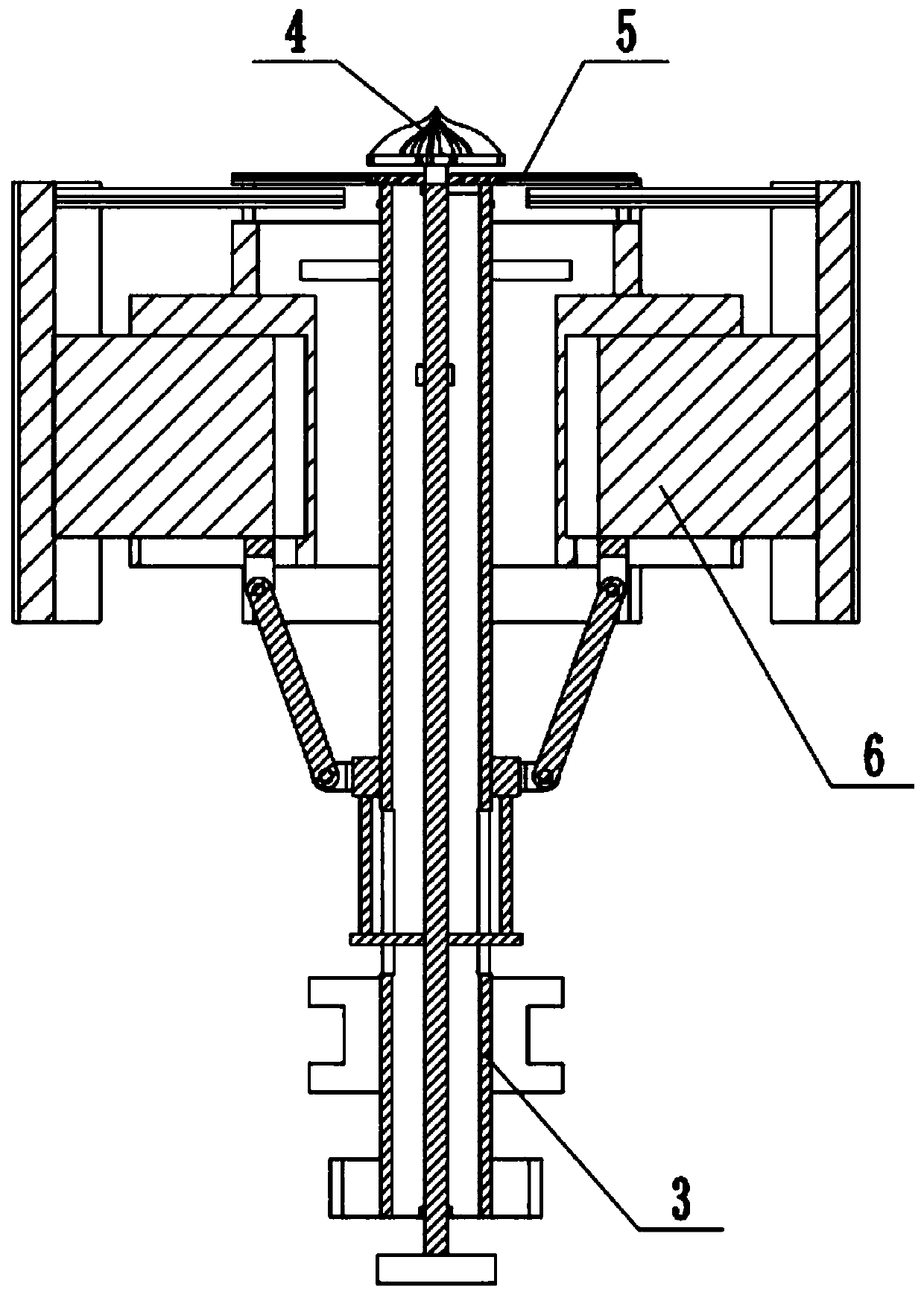
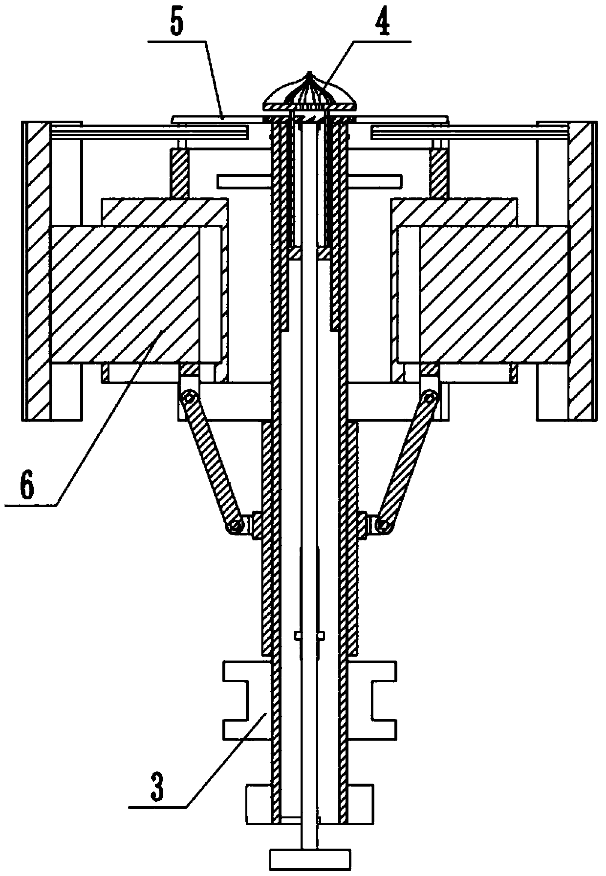
[0031] Combine below Figure 1-13 Describe this embodiment, a construction wall ditch digging device, including a support frame 1, a horizontal and vertical adjustment mechanism 2, a rotary drive member 3, a central drilling member 4, a main planing cutter head 5 and an inner wall grinding assembly 6, the The horizontal and vertical adjustment mechanism 2 is connected to the support frame 1, the rotary drive part 3 is clearance fit on the horizontal and vertical adjustment mechanism 2, the rotary drive part 3 and the horizontal and vertical adjustment mechanism 2 are connected by belt transmission, and the center drilling part 4 is connected by sliding fit. In the rotary driving part 3, the central drilling part 4 is connected with the rotary driving part 3 through thread fit, the main planing cutter head 5 is fixedly connected to the upper end of the rotary driving part 3, and the upper end of the inner wall grinding assembly 6 is fixedly connected to the rotary driving part ...

specific Embodiment approach 2

[0033] Combine below Figure 1-9 To illustrate this embodiment, the support frame 1 includes a door-shaped base 1-1, a universal wheel 1-2, a guide plate 1-3, an I-shaped plate 1-4, a longitudinal adjustment screw 1-5, and a motor Ⅰ1-6, L-shaped screw seat plate 1-7, ground screw 1-8 and guide rod 1-9; the two ends of the door-shaped base 1-1 are respectively fixedly connected with two universal wheels 1-2, two The guide plate 1-3 is symmetrically fixedly connected to the rear end of the door-shaped base 1-1, the I-shaped plate 1-4 is fixedly connected to the two guide plates 1-3, and the two ends of the longitudinal adjustment screw 1-5 are respectively Rotately connected to the door-shaped base 1-1 and the I-shaped plate 1-4 through the bearing with seat, and the two ends of the guide rod 1-9 are fixedly connected to the I-shaped plate 1-4 and the door-shaped base 1-4 respectively. 1, the longitudinal adjustment screw 1-5 and the guide rod 1-9 are located at the front end o...

specific Embodiment approach 3

[0035] Combine below Figure 1-9 To illustrate this embodiment, the horizontal and vertical adjustment mechanism 2 includes a motor II 2-1, a driving pulley 2-2, a shift fork 2-3, two left and right L-shaped linkage rods 2-4, and a horizontal adjustment screw 2-5. , left bracket 2-6, motor III 2-7, right slide bar 2-8 and right bracket 2-9; the output shaft of motor II 2-1 is fixedly connected to driving pulley 2-2, and motor II 2-1 passes through the motor frame Fixedly connected to two shift forks 2-3, the two shift forks 2-3 are arranged symmetrically, the outer ends of the two shift forks 2-3 are fixedly connected to an L-shaped linkage rod 2-4, and the left L-shaped linkage The rod 2-4 is connected to the horizontal adjustment screw 2-5 through thread fit, the horizontal adjustment screw 2-5 is rotatably connected to the left bracket 2-6 through the bearing with seat, and the motor III 2-7 is fixedly connected to the On the left bracket 2-6, the output shaft of the motor...


PUM


Abstract

The invention discloses a building wall groove digging device and relates to the technical field of engineering machinery. The building wall groove digging device comprises a supporting frame, a transverse and longitudinal adjusting mechanism, a rotary driving part, a center hole drilling part, a main digging cutter disc and an inner wall grinding assembly. The building wall groove digging device has the beneficial technical effects that digging is performed from the lower portion, broken wall is automatically discharged downwards under the action of gravity, the process of conveying out the broken wall from inside to outside if digging is performed from top to bottom is omitted, the center hole drilling part is lifted upwards while the inner wall grinding assembly extends outwards, and the device is suitable for hard walls. The transverse and longitudinal adjusting mechanism is connected to the supporting frame, the rotary driving part is in clearance fit with the transverse and longitudinal adjusting mechanism, the rotary driving part is in transmission connection with the transverse and longitudinal adjusting mechanism through a belt; the center hole drilling part is connected into the rotary driving part in a sliding fit mode; the center hole drilling part is matched and connected with the rotary driving part through screw threads; the main digging cutter disc is fixedly connected to the upper end of the rotary driving part; and the upper end of the inner wall grinding assembly is fixedly connected to the rotary driving part.

Description

technical field [0001] The invention relates to the technical field of engineering machinery, in particular to a construction wall ditch digging device. Background technique [0002] The existing patent No. CN201520430642.5 is the underground diaphragm wall entering rock trough forming equipment. This utility model relates to the technical field of underground diaphragm wall entering rock trough forming. It discloses the construction equipment for underground diaphragm wall entering rock trough forming. The bedrock includes strongly weathered rock, For medium weathered rock and slightly weathered rock, the construction equipment for trenching underground diaphragm wall into rock includes grab buckets for grabbing soil and forming trenches in the surface soil, undisturbed soil layers above the bedrock and rotary drilling barrels for drilling holes in strongly weathered rocks , Drilling and coring in moderately weathered rocks to form a pick drill barrel for rock entry holes a...

Claims


Application Information

Patent Timeline
Patent Type & Authority Applications(China)
IPC IPC(8): E02F5/02E02D5/18
CPCE02D5/187E02F5/027
Inventor 陈铭勋
Owner 安徽天驰建工集团有限公司
Why Eureka
Try Eureka