Core pulling mechanism of automobile rear door handle

A core-pulling mechanism and back door technology, which is applied to household components, household appliances, and other household appliances, can solve the problems of high cost, low efficiency, and inability to pull grooves and undercut cores at one time, and achieve low cost and high efficiency. high effect

Active Publication Date: 2019-10-18
NINGBO FANGZHENG TOOL
View PDF2 Cites 3 Cited by
  • Summary
  • Abstract
  • Description
  • Claims
  • Application Information

AI Technical Summary

Problems solved by technology

[0002] With the development of science and technology, cars have gradually become a common means of transportation for people. The back door handle is one of the components of the car. Generally, the back door handle cover is formed by injection molding. The inner side of the back door handle cover is provided with a rectangular column. A groove is set inside the rectangular column, and an undercut is provided on the top of the groove. During injection molding, the groove and the undercut need to be core-pulled. According to the existing technology, the rear door handle cover mold needs two molds to form the groove and the underside respectively. Buckle, cannot pull the groove and undercut core at one time, high cost and low efficiency

Method used


Image

  • Core pulling mechanism of automobile rear door handle
  • Core pulling mechanism of automobile rear door handle
  • Core pulling mechanism of automobile rear door handle

Examples


Embodiment Construction

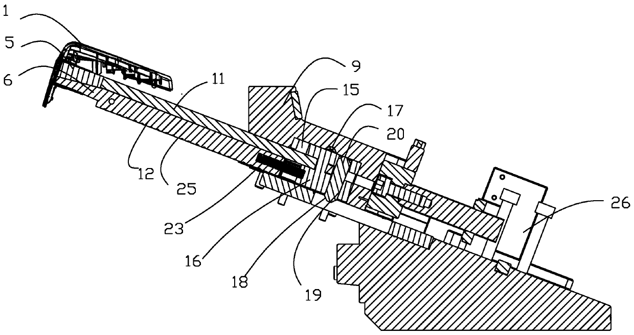
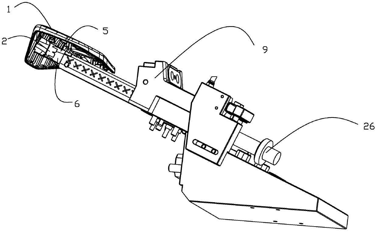
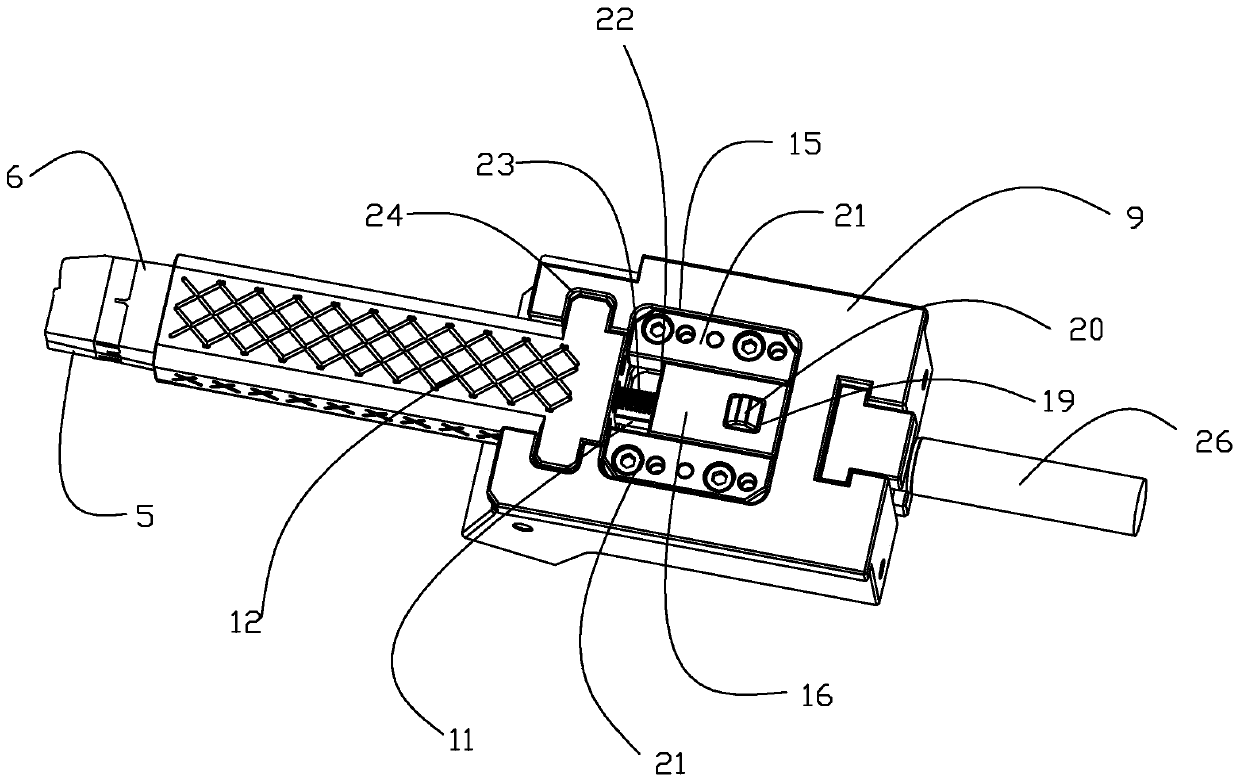
[0022] The present invention will be further described below in conjunction with the accompanying drawings and specific embodiments.

[0023] As shown in the figure, the present invention provides an automobile rear door handle core-pulling mechanism, which includes a product 1 and a lower template 8. The inner wall of the product 1 is provided with a rectangular column 2, and the inside of the rectangular column 2 is along the axis of the rectangular column 2. The direction is provided with a groove 3, and the top of the groove 3 is provided with an undercut 4, which also includes a first mold core 5 for forming the upper part of the groove 3, and a second mold core 5 for forming the lower part of the groove 3. The mold core 6, the large slider 9 and the cylinder 26, the upper surface of the first mold core 5 is provided with a bump 7 protruding from the upper surface of the first mold core 5 for forming the undercut 4, and the upper surface of the lower template 8 A first op...


PUM


Abstract

The invention discloses a core pulling mechanism of an automobile rear door handle. The core pulling mechanism comprises a product, a lower die plate, a first mold core, a second mold core, a large sliding block and an air cylinder, wherein a rectangular post is arranged on the inner side wall of the product, a groove is formed in the rectangular post in the axis direction of the rectangular post,a buckle is arranged on the top of a groove, the first mold core is used for forming the upper part of the groove, the second mold core is used for forming the lower part of the groove, a bulged block which is used for forming the buckle and protrudes from the upper surface of the first mold core is arranged on the upper surface of the first mold core, a first open groove is formed in the lower die plate, the large sliding block can be matched with the interior of the first open groove in a forward and backward sliding mode, the large sliding block is driven by the air cylinder, a first sliding block is arranged on one end, which is away from the product, of the first mold core, a second sliding block is arranged on one end, which is away from the product, of the second mold core, and oneend, which is away from the product, of the second sliding block is arranged on the large sliding block. The core pulling mechanism of the automobile rear door handle has the advantages of low cost and high efficiency.

Description

technical field [0001] The invention relates to the field of injection molds, in particular to a core-pulling mechanism for an automobile rear door handle. Background technique [0002] With the development of science and technology, cars have gradually become a common means of transportation for people. The back door handle is one of the components of the car. Generally, the back door handle cover is formed by injection molding. The inner side of the back door handle cover is provided with a rectangular column. A groove is set inside the rectangular column, and an undercut is provided on the top of the groove. During injection molding, the groove and the undercut need to be core-pulled. According to the existing technology, the rear door handle cover mold needs two molds to form the groove and the underside respectively. Buckle, the groove and undercut core cannot be pulled at one time, the cost is high and the efficiency is low. Contents of the invention [0003] The te...

Claims


Application Information

Patent Timeline
Patent Type & Authority Applications(China)
IPC IPC(8): B29C45/33B29L31/30
CPCB29C45/332B29L2031/3029
Inventor 王文振方永杰张献文徐威宇孙建新郑立剑金欢冉耘卉仇碧波左伟民
Owner NINGBO FANGZHENG TOOL
Why Eureka
Try Eureka