
A slidable and tilt-assisted lifting device with a bracket

A lifting device and sliding technology, which is applied in the field of aerospace launch, can solve the problems such as the difficulty of aligning the vertical oil cylinder and the pin hole of the launch tube, and achieve the effects of reducing labor intensity, improving efficiency, and improving safety

Active Publication Date: 2021-07-30
BEIJING INST OF SPACE LAUNCH TECH +1
View PDF4 Cites 0 Cited by
  • Summary
  • Abstract
  • Description
  • Claims
  • Application Information

AI Technical Summary

Problems solved by technology

[0003] The technical problem to be solved by the present invention is to provide a lifting device with a slidable and tiltable bracket, which can lift the erecting cylinder conveniently and quickly, and solve the difficulty of aligning the erecting cylinder with the pin hole of the launch tube Big problems, reduce labor intensity, improve efficiency, and significantly improve safety during operation

Method used


Image

  • A slidable and tilt-assisted lifting device with a bracket
  • A slidable and tilt-assisted lifting device with a bracket
  • A slidable and tilt-assisted lifting device with a bracket

Examples


Embodiment Construction

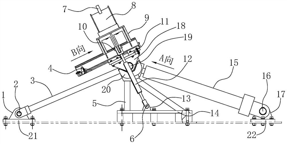
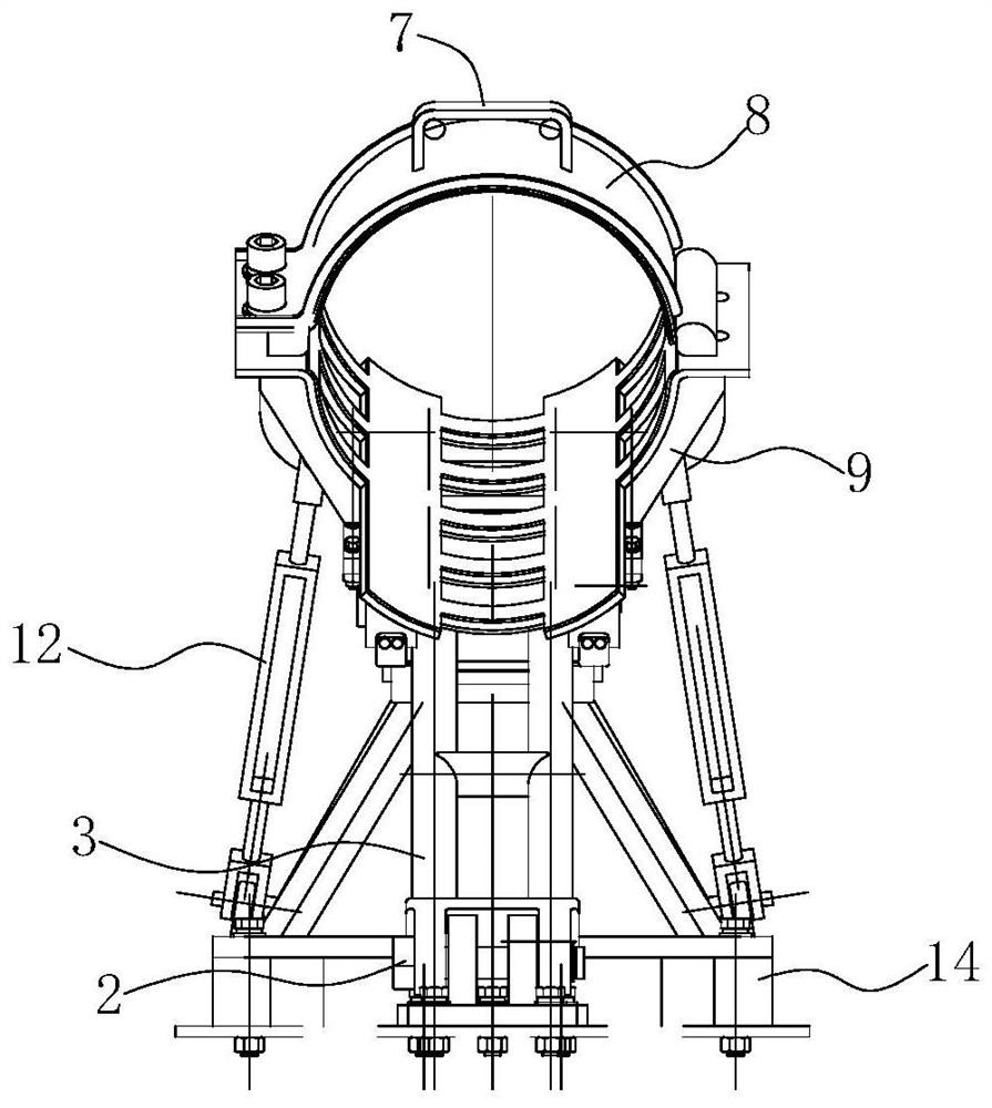
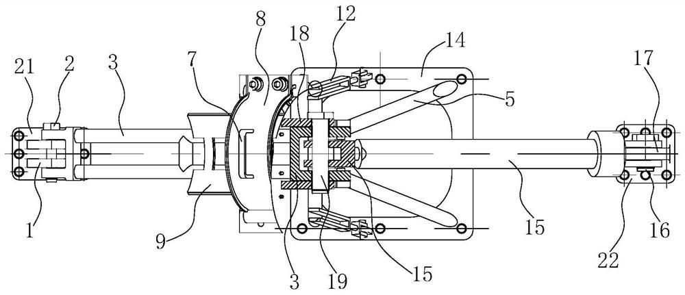
[0019] Such as figure 1 shown, combined with figure 2 , 3 As shown, the bracket of the present invention can slide and tilt the booster type lifting device, including a rotary bracket 3, a drive cylinder 15 and a first lug 18, the lower end of the rotary bracket 3 is hinged to the first support 21, the The lower end of the drive cylinder 15 is hinged to the second support 22 , and the upper ends of the slewing bracket 3 and the drive cylinder 15 are both hinged to the first lug 18 on which the bracket 9 is slidably mounted.

[0020] The bracket of the present invention can be slidable and tilted to assist the lifting device, wherein the bracket 9 is provided with a first semicircular groove, and the first semicircular groove is used for placing a vertical oil cylinder.

[0021] The bracket of the present invention can slide and tilt the booster lifting device, wherein the bracket 9 is provided with a cover plate 8, one side of the cover plate 8 is hinged with the bracket 9,...


PUM


Abstract

The invention discloses a lifting device with a slidable and tiltable bracket, which includes a slewing bracket, a drive cylinder and a first lug, the lower end of the slewing bracket is hinged to the first support, and the drive cylinder The lower end is hinged to the second support, and the upper ends of the slewing bracket and the drive cylinder are both hinged to the first lug on which a bracket is slidably mounted. Its purpose is to provide a lifting device with a slidable and tiltable bracket, which can lift the erecting cylinder conveniently and quickly, and solve the problem of difficulty in aligning the erecting cylinder with the pin hole of the launch tube. Reduce labor intensity, improve efficiency, and significantly improve safety during operation.

Description

technical field [0001] The invention relates to the field of aerospace launch technology, in particular to a slidable tilting booster lifting device with a bracket. Background technique [0002] In the field of space launch, the erection cylinder needs to be used during the erection process of the launch tube, and the erection cylinder needs to be fixedly connected to the launch tube and the launch vehicle. The pin holes of the oil cylinder and the pin holes on the launch tube are accurately positioned to ensure the pin threading process. This requires proper swinging of the erecting cylinder. Since the weight of the erecting cylinder is generally about 2 tons, it is impossible to use manpower to align the pin holes. The pin hole alignment is often carried out by hoisting. Due to the limited accuracy of hoisting , This method usually requires a long time for the centering process, it is difficult to manually complete the pin hole centering, the labor intensity is high, the ...

Claims


Application Information

Patent Timeline
Patent Type & Authority Patents(China)
IPC IPC(8): B64G5/00
CPCB64G5/00
Inventor 杨卫杰刘佳张博宇廖军白文龙
Owner BEIJING INST OF SPACE LAUNCH TECH
Learn More