Electric power construction maintenance tool

A technology for electric power construction and appliances, which is applied in the direction of hoisting devices, lifting frames, etc., can solve the problems of inability to lift and lower heavy objects and high-altitude operations, resources are not fully utilized, and equipment labor costs are high, so as to reduce equipment and labor costs and quickly The effect of convenient fixed clamping and simple structure

Inactive Publication Date: 2019-10-18
国网山东省电力公司招远市供电公司
View PDF10 Cites 3 Cited by
  • Summary
  • Abstract
  • Description
  • Claims
  • Application Information

AI Technical Summary

Problems solved by technology

[0004] The purpose of the present invention is to solve the problems in the prior art that cannot lift and lower heavy objects and work at high altitude due to the lack of supports. Therefore, in the above-mentioned application occasions, equipment such as cranes and aerial work ladders are required at the same time. Not only the equipment and labor costs are high , and occupies a place, the resource has not been fully utilized, so it cannot meet the shortcomings of people's needs, and a kind of power construction maintenance tool is proposed

Method used


Image

  • Electric power construction maintenance tool
  • Electric power construction maintenance tool
  • Electric power construction maintenance tool

Examples


Embodiment 1

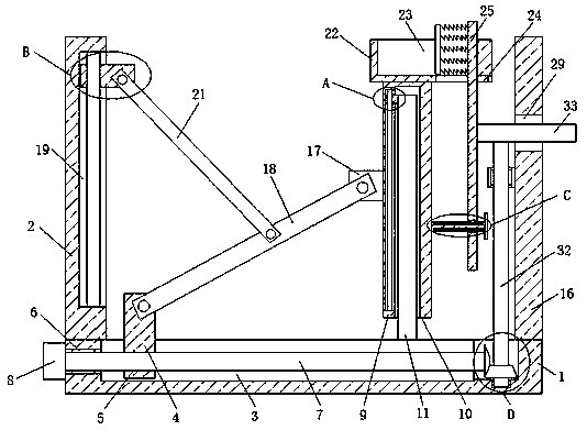
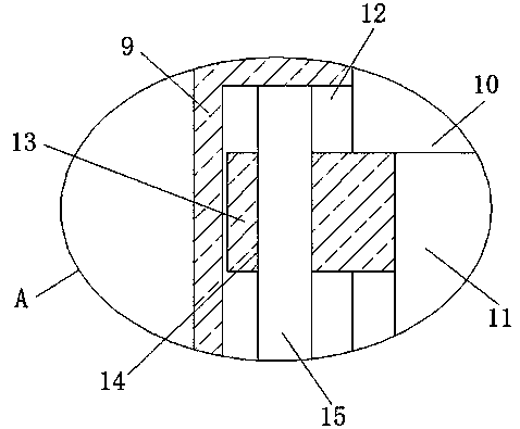
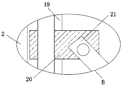
[0027] refer to Figure 1-6 , a kind of electric power construction overhaul appliance, comprises fixed base 1, and the top of fixed base 1 is fixedly installed with first rod 2 and second rod 16, and the top of fixed base 1 is provided with first chute 3, and inside first chute 3 The first slider 4 is slidably installed, and the first slider 4 is provided with a threaded hole 5, and one side of the fixed base 1 is provided with a first rotation hole 6, and the first chute 3 and the first rotation hole 6 are installed in rotation. There is the same threaded rod 7, one end of the threaded rod 7 passes through the threaded hole 5 and is threadedly connected with the threaded hole 5, a servo motor 8 is fixedly installed on one side of the fixing seat 1, and one end of the threaded rod 7 extends through the first rotation hole 6 To the outside of the fixed seat 1 and fixedly connected with the output shaft of the servo motor 8, a sliding plate 9 is arranged above the fixed seat 1,...

Embodiment 2

[0036] refer to Figure 1-6 , a kind of electric power construction overhaul appliance, comprises fixed base 1, and the top of fixed base 1 is fixedly connected with first rod 2 and second rod 16 by bolt, and the top of fixed base 1 is provided with first chute 3, and the first chute 3 is slidably installed with a first slider 4, the first slider 4 is provided with a threaded hole 5, one side of the fixed seat 1 is provided with a first rotation hole 6, and the first slide groove 3 and the first rotation hole 6 The same threaded rod 7 is installed in rotation, and one end of the threaded rod 7 runs through the threaded hole 5 and is threadedly connected with the threaded hole 5. One side of the fixing seat 1 is fixedly connected with a servo motor 8 by bolts, and one end of the threaded rod 7 runs through the first The rotation hole 6 extends to the outside of the fixed seat 1 and is fixedly connected with the output shaft of the servo motor 8. A sliding plate 9 is arranged ab...


PUM


Abstract

The invention belongs to the field of maintenance tools, and particularly relates to an electric power construction maintenance tool. In view of the problems that due to supporting object lack in existing electric power construction, heavy objects cannot be lifted and aerial work cannot be carried out, in the above application occasions, equipment such as a crane and an aerial work ladder is needed at the same time, the equipment cost and the labor cost are high, the occupied area is large, and resources are not fully utilized, according to the following scheme, the electric power constructionmaintenance tool comprises a fixed seat, a first rod and a second rod are fixedly arranged at the top of the fixed seat, a first sliding groove is formed in the top of the fixed seat, a first slidingblock is slidably arranged in the first sliding groove, and a threaded hole is formed in the first sliding block. According to the electric power construction maintenance tool, the structure is simple, the operation is convenient, the heavy objects can be quickly and conveniently lifted and different sizes of heavy objects can be fixed and clamped, the situation that slippage of the heavy objectsin the lifting process causes potential safety hazards to people is prevented, the equipment cost and the labor cost are reduced, the occupied area is small, and the resources are fully utilized, sothat the requirements of people are met.

Description

technical field [0001] The invention relates to the technical field of maintenance tools, in particular to a power construction maintenance tool. Background technique [0002] Application No. 201611151977.9 discloses a maintenance tool for electric power construction, which includes an outer ladder frame and an inner ladder frame arranged inside the outer ladder frame. The U-shaped openings of the two vertical beams are arranged facing each other. The two ends of the inner ladder frame are respectively clamped on the inside of the vertical beams and can slide relative to the vertical beams. Mounting holes arranged at equal intervals are arranged on the vertical beams. A mounting plate is arranged inside the mounting hole, and the mounting plate is located on the end surface of the mounting hole close to the U-shaped opening of the vertical beam. The present invention adopts a two-layer ladder structure inside and outside, so that the inner ladder frame can be extended along ...

Claims


Application Information

Patent Timeline
Patent Type & Authority Applications(China)
IPC IPC(8): B66F7/06B66F7/28
CPCB66F7/0691B66F7/28
Inventor 王亦军华海娣张亚婷于洋王妮妮李锋赵鹏王利芹李玉林段艳芹史学锋张岩雷朱琳李长峰刘希荣李晓庆薛金训秦德展
Owner 国网山东省电力公司招远市供电公司
Why Eureka
Try Eureka