Backlight module and display device

A backlight module and backplane technology, applied in the direction of light guides, optics, optical components, etc., can solve the problems that light cannot effectively pass through the optical film structure, the camera device cannot effectively capture light, and the optical film structure has low transparency. , to achieve the effect of increasing the camera effect, eliminating the need for opening steps, and improving the uniformity of light

Inactive Publication Date: 2019-10-18
WUHAN CHINA STAR OPTOELECTRONICS TECH CO LTD
View PDF8 Cites 6 Cited by
  • Summary
  • Abstract
  • Description
  • Claims
  • Application Information

AI Technical Summary

Problems solved by technology

[0002] With the continuous development of display technology, the performance of mobile phones is becoming more and more powerful, but due to the existence of mobile phone cameras, microphones, etc., the conversion from narrow bezels to full screens cannot be fully realized.
[0003] In the existing backlight module, due to the low transparency of the optical film structure, the transparency of the traditional backlight module is not high, the light cannot effectively pass through the optical film structure, and the camera device cannot effectively capture light, etc.

Method used


Image

  • Backlight module and display device
  • Backlight module and display device
  • Backlight module and display device

Examples


Embodiment 1

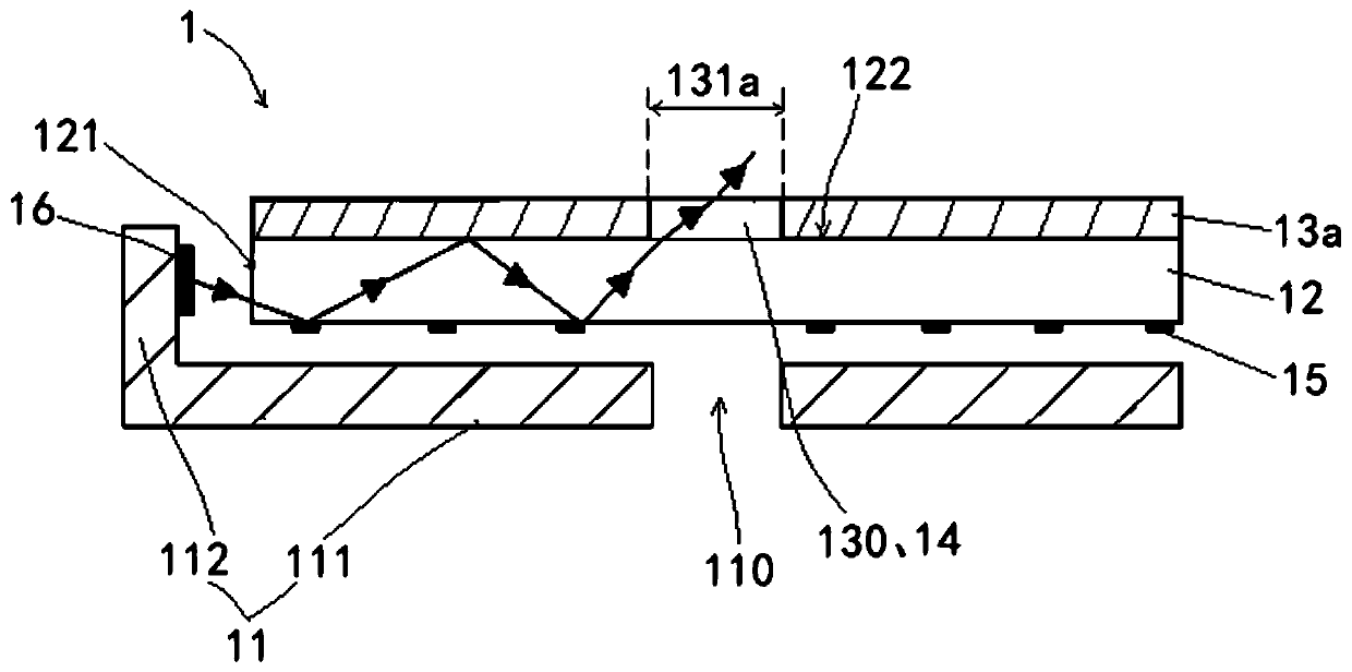
[0033] Such as figure 1 As shown, the backlight module 1 of the present invention includes a backplane 11 , a light guide plate 12 , an optical film 13 a , a transparent film 14 , a reflection sheet 15 and a light source 16 .

[0034] The back plate 11 has a through hole 110 for providing a light-transmitting channel for the camera. The entire backboard 11 includes a bottom board 111 and side boards 112 vertically connected to sides of the bottom board 111 . In this embodiment, the back plate 11 is formed integrally with iron, aluminum or other metals or alloys, and the bottom plate 111 and the side plates 112 form a cavity.

[0035] The light guide plate 12 is disposed in the cavity surrounded by the back plate 11 , specifically, the light guide plate 12 is disposed above the bottom plate 111 in parallel. Wherein the light guide plate 12 has a light incident surface 121 and a light exit surface 122, the side of the light guide plate 12 facing away from the light exit surfac...

Embodiment 2

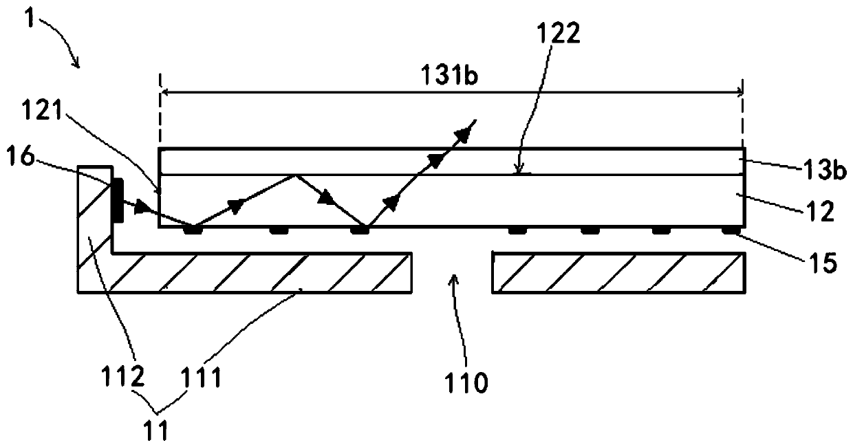
[0046] Such as image 3 As shown, the backlight module 1 of the present invention includes a backplane 11 , a light guide plate 12 , an optical film 13 b , a reflection sheet 15 and a light source 16 .

[0047] The back plate 11 has a through hole 110 for providing a light-transmitting channel for the camera. The entire backboard 11 includes a bottom board 111 and side boards 112 vertically connected to sides of the bottom board 111 . In this embodiment, the back plate 11 is formed integrally with iron, aluminum or other metals or alloys, and the bottom plate 111 and the side plates 112 form a cavity.

[0048] The light guide plate 12 is disposed in the cavity surrounded by the back plate 11 , specifically, the light guide plate 12 is disposed above the bottom plate 111 in parallel. Wherein the light guide plate 12 has a light incident surface 121 and a light exit surface 122, the side of the light guide plate 12 facing away from the light exit surface 122 faces the bottom p...


PUM

PropertyMeasurementUnit
transmittivityaaaaaaaaaa

Abstract

The invention discloses a backlight module, which comprises: a back plate with a through hole for providing a light transmission channel for a camera; and an optical film arranged on the back plate, where a transparent area is arranged on the optical film, and the through hole corresponds to the transparent area. According to the backlight module and the display device, an opening corresponding tothe through hole in the back plate is formed in the traditional optical film, and a transparent film is arranged in the opening, so that the light transmittance of light is increased, and the camerashooting effect is improved; a light guide plate is polished, so that the transparency of the surface of the light guide plate is improved, the light uniformity is effectively improved, and the lightintensity is increased; or the whole optical film is set to be a transparent optical film, so that the light transmittance and the camera shooting effect of are improved, and meanwhile, a tapping stepis also omitted.

Description

technical field [0001] The invention relates to the fields of displays and the like, in particular to a backlight module and a display device. Background technique [0002] With the continuous development of display technology, the performance of mobile phones is becoming more and more powerful, but due to the existence of mobile phone cameras, microphones, etc., the conversion from narrow bezels to full screens cannot be fully realized. [0003] In the existing backlight module, due to the low transparency of the optical film structure, the transparency of the traditional backlight module is not high, the light cannot effectively pass through the optical film structure, and the camera device cannot effectively capture the light. Contents of the invention [0004] In order to solve the above-mentioned technical problems: the present invention provides a backlight module and a display device. The optical film is set as a transparent area corresponding to the imaging area to...

Claims


Application Information

Patent Timeline
Patent Type & Authority Applications(China)
IPC IPC(8): G02F1/13357G02B6/00
CPCG02B6/0035G02F1/1336G02F1/133606
Inventor 钱丽琼余文强
Owner WUHAN CHINA STAR OPTOELECTRONICS TECH CO LTD
Why Eureka
Try Eureka