Direct-drive traction motor rotating shaft sleeving device and method

A technology for traction motors and shafts, which is applied in the direction of electromechanical devices, manufacturing motor generators, electrical components, etc., can solve the problems of high cost, unsatisfactory, and failure to use hydraulic presses, etc., to achieve reduced damage, small press-fitting displacement, and packaging process Safe and reliable effect

Pending Publication Date: 2019-10-18
CSR ZHUZHOU ELECTRIC CO LTD
View PDF1 Cites 0 Cited by
  • Summary
  • Abstract
  • Description
  • Claims
  • Application Information

AI Technical Summary

Problems solved by technology

[0002] At present, the traction motor sleeve shaft device is equipped with a hydraulic press, and the method of using a hydraulic press to set the rotating shaft has the following disadvantages: 1. It is uneconomical, and it is necessary to purchase a special hydraulic press. The operating cost is high; 2. The scope of application is limited. Motors whose length exceeds the stroke will not be able to use hydraulic presses for shaft assembly
The new direct-drive permanent magnet traction motor adopts a coaxial structure with the shaft of the vehicle, and the length of the shaft reaches 2.2m. Conventional hydraulic machines cannot meet the needs of this type of motor shaft assembly. The cost of purchasing an unconventional hydraulic machine is high. For this small batch production of motors say no need at all

Method used


Image

  • Direct-drive traction motor rotating shaft sleeving device and method
  • Direct-drive traction motor rotating shaft sleeving device and method
  • Direct-drive traction motor rotating shaft sleeving device and method

Examples


Embodiment Construction

[0030] Combine below Figure 1 to Figure 6 Embodiments of the present invention are described in detail.

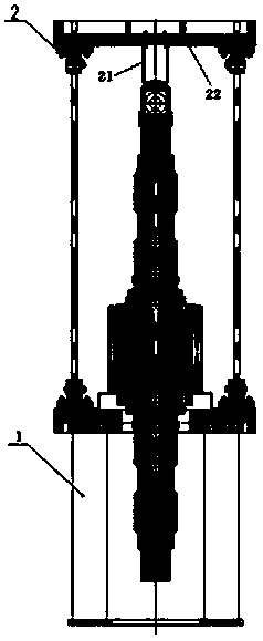
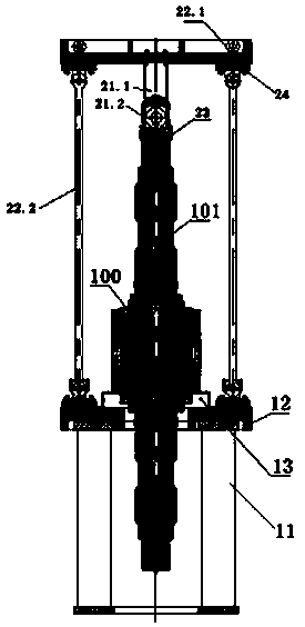
[0031] Direct drive traction motor rotating shaft assembly device, including supporting and positioning assembly 1 for supporting and positioning the rotor core 100 arranged vertically and press-fitting assembly 2 for pressing the rotating shaft 101 into the rotor core 100, the rotor core 100 is vertically arranged Positioned on the supporting positioning assembly 1, the rotating shaft 101 is lowered into the rotor core and one end extends into the supporting positioning assembly 1, the press-fit assembly 2 is coaxially connected above the supporting positioning assembly 1, and the rotating shaft 101 is aligned along the central axis of the rotating shaft 101. Press down.

[0032] The direct drive traction motor rotating shaft assembly device described above includes a support positioning assembly 1 and a press-fit assembly 2, the support positioning assembly 1 is used t...


PUM


Abstract

The invention relates to a direct-drive traction motor rotating shaft sleeving device and method. The direct-drive traction motor rotating shaft sleeving device comprises a supporting and positioningassembly used for supporting and positioning a rotor core so as to make the rotor core arranged along a vertical direction and a pressing assembly used for pressing a rotating shaft into the rotor core; the rotor core is positioned on the supporting and positioning assembly along the vertical direction; the rotating shaft is arranged into the rotor core, and one end of the rotating shaft extends into the supporting and positioning assembly; the pressing assembly is coaxially connected above the supporting and positioning assembly; and the rotating shaft is pressed downwards along the central axis of the rotating shaft. According to the direct-drive traction motor rotating shaft sleeving device and method of the invention, the supporting and positioning assembly and the pressing assembly are used in a matched manner, so that the rotor core can sleeve the rotating shaft, and external pressing equipment is not adopted during a whole sleeving process, and therefore, the sleeving device issafe, reliable, economical and practical; the inner diameter of the rotor core is increased through a heating mode, so that the axial displacement of the rotating shaft during the arrangement of the rotating shaft in the rotor core is increased, and therefore, the axial friction pressing displacement of the rotating shaft in the rotor core is smaller, damage to the rotating shaft in the sleeving process is reduced, and the rotating shaft can be reliably, safely, efficiently and nondestructively sleeved with the rotor core.

Description

technical field [0001] The invention relates to a direct-drive traction motor rotating shaft assembly device and method, which are used for the assembly of the rotating shaft and rotor core in the direct-drive traction motor. Background technique [0002] At present, the traction motor sleeve shaft device is equipped with a hydraulic press, and the method of using a hydraulic press to set the rotating shaft has the following disadvantages: 1. It is uneconomical, and it is necessary to purchase a special hydraulic press. The operating cost is high; 2. The scope of application is limited. Motors whose length exceeds the stroke will not be able to use a hydraulic press for shaft assembly. The new direct-drive permanent magnet traction motor adopts a coaxial structure with the shaft of the vehicle, and the length of the shaft reaches 2.2m. Conventional hydraulic machines cannot meet the needs of this type of motor shaft assembly. The cost of purchasing an unconventional hydrauli...

Claims


Application Information

Patent Timeline
Patent Type & Authority Applications(China)
IPC IPC(8): H02K15/00
CPCH02K15/00
Inventor 夏红勇杨莺贺北平王山兰万玲熊文浩邓先平曹家熙
Owner CSR ZHUZHOU ELECTRIC CO LTD
Why Eureka
Try Eureka