AI technical title is built by PatSnap AI team. It summarizes the technical point description of the patent document.
A washing machine and door lock technology, which is applied to other washing machines, washing devices, textiles and papermaking, etc., to achieve the effect of compact structure and high assembly efficiency
Active Publication Date: 2019-10-22
WUXI LITTLE SWAN ELECTRIC CO LTD
View PDF6 Cites 3 Cited by
Summary
Abstract
Description
Claims
Application Information
AI Technical Summary
This helps you quickly interpret patents by identifying the three key elements:
Problems solved by technology
Method used
Benefits of technology
Problems solved by technology
However, in this door lock mode, holes must be made on the workbench and the door cover. In actual use, it is necessary to protect the water leakage at the opening, so that the door lock water leakage prevention has become one of the problems that people in the field need to solve urgently. one
Method used
Image
Click on the blue label to locate the original text in one second.
Reading with bidirectional positioning of images and text.
Examples
Embodiment 1
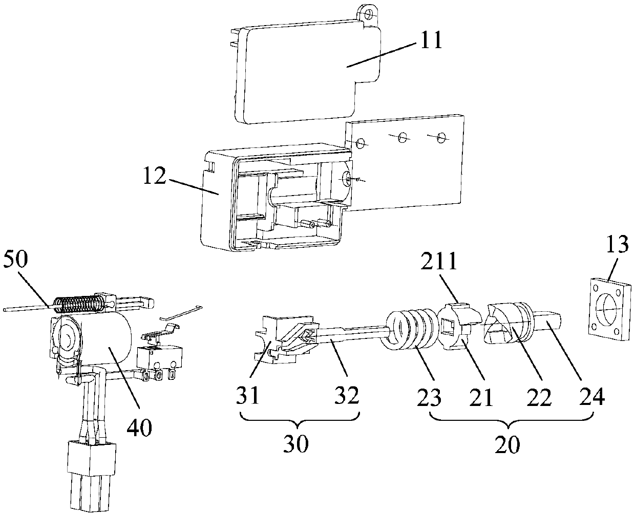
[0079] Embodiment one (as Figure 1 to Figure 6 shown)
[0080] The fixing part 21 is located between the limiting part 31 and the rotating part 22, and the fixing part 21 is provided with an escape hole, and the limiting shaft 32 is inserted into the shaft hole 221 through the avoiding hole, as Figure 1 to Figure 6 shown.
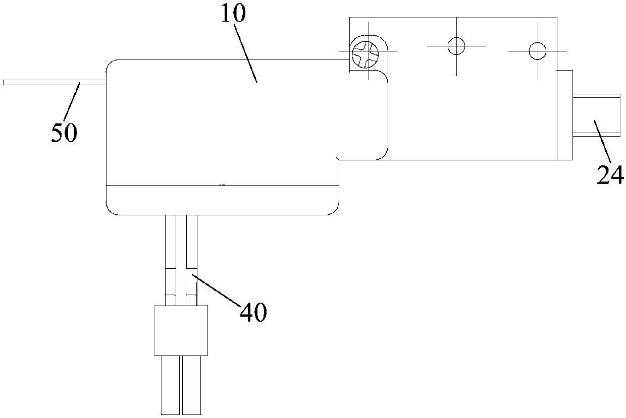
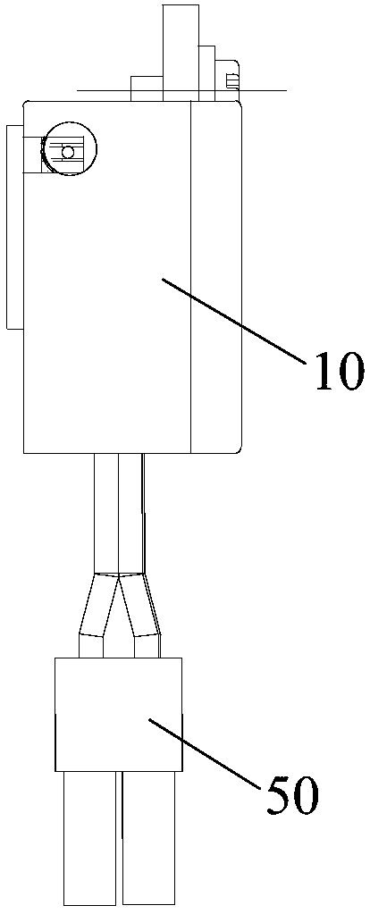
[0081] Furthermore, the damping door lock 1 is installed in the rotating shaft 202 of the door cover 2, and is fixedly connected with the door cover 2 through the first connection part, and fixedly connected with the body workbench 3 through the second connection part.
[0082] The fixed part 21 is located between the limiting part 31 and the rotating part 22, and the limiting shaft 32 needs to pass through the fixing part 21 to be inserted into the shaft hole 221 on the rotating part 22, so a corresponding avoidance hole is opened in the middle of the fixing part 21 , to avoid the limit shaft 32; at this time, the rotating part 22 is relatively close t...
Embodiment 2
[0084] Embodiment 2 (not shown in the figure)
[0085] The difference from Embodiment 1 is that the rotating part 22 is located between the limiting part 31 and the fixing part 21, the fixing part 21 is sleeved on the second connecting part, and can rotate relative to the second connecting part, and the second connecting part passes through The fixing part 21 is fixedly connected with the workbench of the machine body.
[0086] The rotating part 22 is located between the limiting part 31 and the fixing part 21, and the fixing part 21 is relatively close to the connecting part of the body and the door cover 2, so the second connecting part needs to pass through the fixing part 21 to be fixedly connected with the workbench of the body. Corresponding holes also need to be opened in the middle of the fixing part 21 to avoid the second connecting part, and at the same time, it is necessary to ensure that the relative rotation between the second connecting part and the fixing part 2...
Embodiment 3
[0087] Embodiment three (not shown in the figure)
[0088] The difference from the first embodiment is that the damping door lock 1 is installed in the workbench 3 of the machine body, and is fixedly connected with the workbench 3 through the first connection part, and is fixedly connected with the door cover 2 through the second connection part.
PUM
Abstract
The invention provides a damping door lock used for a washing machine. The damping door lock comprises a housing, a damper and a lock cylinder, and the housing is provided with a first connecting part; at least part of the damper is installed in the housing and is used for increasing the resistance of a door cover during closure, the damper is provided with a second connecting part capable of rotating relative to the housing, and one of the second connecting part and the first connecting part can be connected with an engine body while the other one can be connected with the door cover to enable the door cover to be connected with the engine body in a pivoted manner; the lock cylinder is installed in the housing and can move reciprocatingly between the lock position and the unlock positionin the housing, and the second connecting part is locked when moving to the lock position to limit the rotation of the second connecting part relative to the housing, and the second connecting part isunlocked when moving to the unlocked position. The damping door lock indirectly limits the rotation of the door cover through the limitation of the lock cylinder to the damper, so that the function of locking the door is realized without opening holes in the door cover or a workbench; the washing machine is more compact in structure, and high assembly efficiency is achieved.
Description
technical field [0001] The invention relates to the technical field of household appliances, in particular to a damping door lock and a washing machine including the damping door lock. Background technique [0002] At present, all washing machines on the market have a safety lock function for safety considerations. Conventional safety locks are arranged on the outer surface of the door cover, and the door lock is installed on the workbench. Through program control, the lock cylinder can extend into the corresponding opening of the door cover to achieve the function of locking the door. However, in this door lock mode, holes must be made on the workbench and the door cover. In actual use, it is necessary to protect the water leakage at the opening, so that the door lock water leakage prevention has become one of the problems that people in the field need to solve urgently. one. Contents of the invention [0003] In order to solve at least one of the above technical proble...
Claims
Application Information
Patent Timeline
Application Date:The date an application was filed.
Publication Date:The date a patent or application was officially published.
First Publication Date:The earliest publication date of a patent with the same application number.
Issue Date:Publication date of the patent grant document.
PCT Entry Date:The Entry date of PCT National Phase.
Estimated Expiry Date:The statutory expiry date of a patent right according to the Patent Law, and it is the longest term of protection that the patent right can achieve without the termination of the patent right due to other reasons(Term extension factor has been taken into account ).
Invalid Date:Actual expiry date is based on effective date or publication date of legal transaction data of invalid patent.

