Damping rod friction coefficient regulation and control structure

A friction coefficient and damping rod technology, which is applied in the field of damping rod friction coefficient control structure, can solve the problems of affecting structural functionality, difficulty in adapting to various use environments, and inability to achieve high efficiency, so as to achieve the effect of controlling the friction coefficient

Inactive Publication Date: 2019-10-22
黄正财
View PDF0 Cites 0 Cited by
  • Summary
  • Abstract
  • Description
  • Claims
  • Application Information

AI Technical Summary

Problems solved by technology

Although the hysteresis damper is widely used at present, the hysteresis damper requires relatively high manufacturing technology
For these traditional dampers, the damping force cannot be adjusted automatically and cannot work efficiently
[0003] Most of the existing damping rods do not have the function of adjusting the damping coefficient, resulting in a fixed damping coefficient, which makes it difficult to adapt to various use environments and affects the structural functionality

Method used


Image

  • Damping rod friction coefficient regulation and control structure
  • Damping rod friction coefficient regulation and control structure
  • Damping rod friction coefficient regulation and control structure

Examples


Embodiment Construction

[0021] The following will clearly and completely describe the technical solutions in the embodiments of the present invention with reference to the accompanying drawings in the embodiments of the present invention. Obviously, the described embodiments are only some, not all, embodiments of the present invention. Based on the technical solutions in the present invention, all other embodiments obtained by persons of ordinary skill in the art without making creative efforts belong to the protection scope of the present invention.

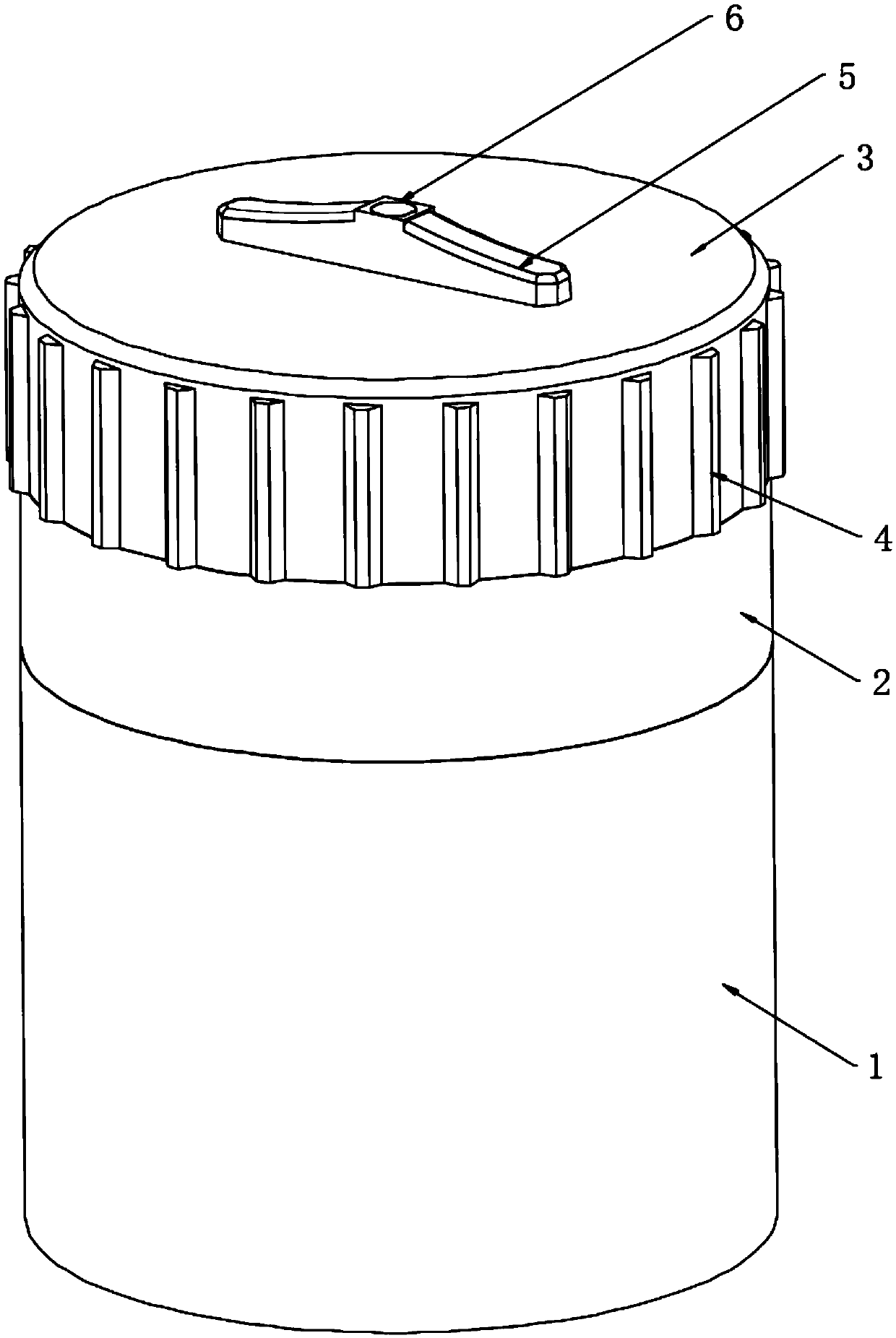
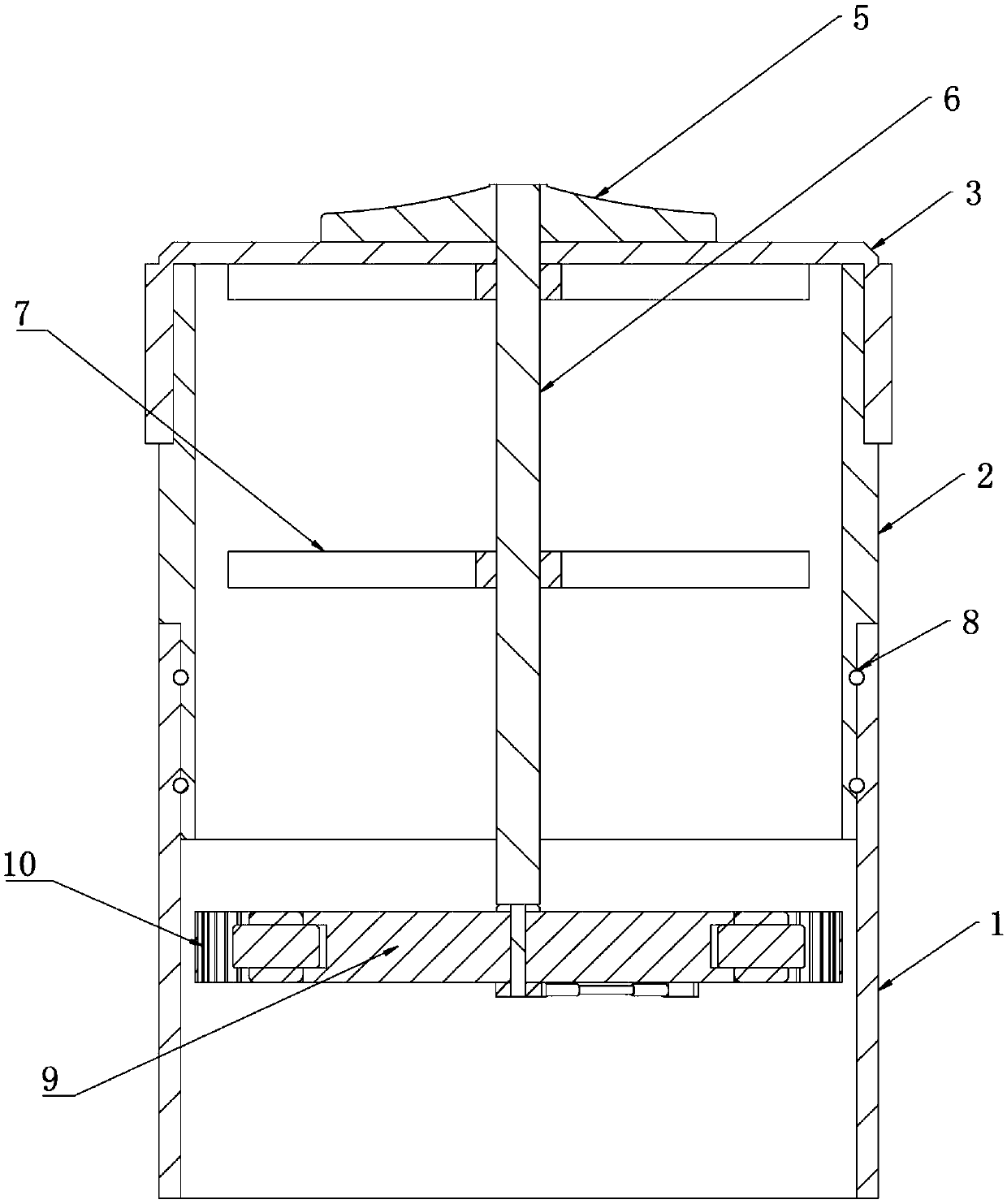
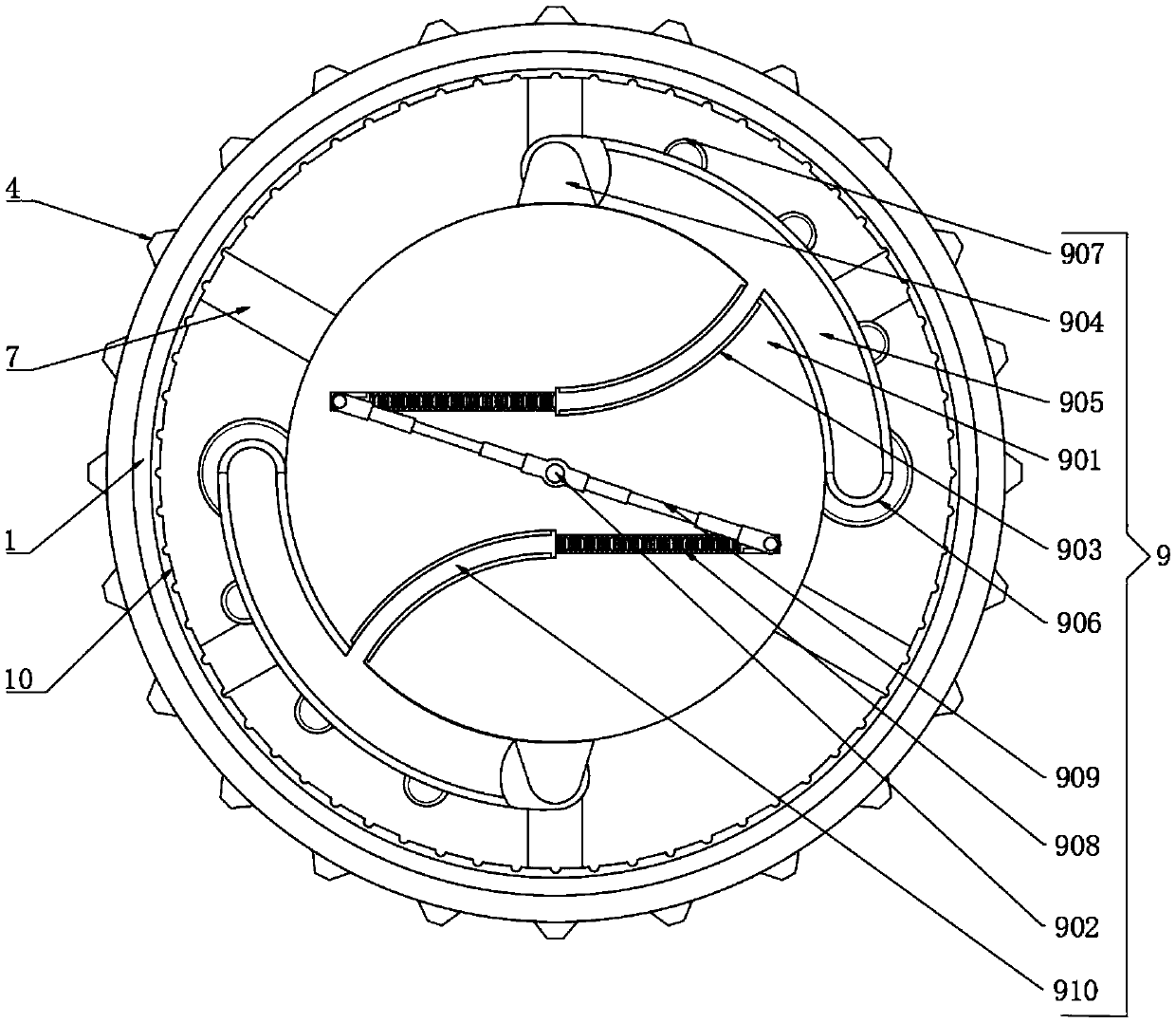
[0022] see Figure 1 to Figure 3 , the present invention provides a technical solution: a damping rod friction coefficient control structure, including a lower rod body 1, an upper rod body 2 is placed above the lower rod body 1, and a rotating cover plate 3 is installed on the top of the upper rod body 2, and the rotating cover On the curved surface of the side wall of the plate 3, there are several groups of friction ribs 4 perpendicular to the botto...


PUM


Abstract

The invention discloses a damping rod friction coefficient regulation and control structure comprising a lower rod body. An upper rod body is inserted in the upper portion of the lower rod body, and arotary cover plate is installed at the top of the upper rod body in a sleeving mode. Multiple sets of friction ridges are arranged on the curved face of the side wall of the rotary cover plate evenlyat equal intervals and are perpendicular to the bottom face of the rotary cover plate, and a twisting handle is welded to the top of the rotary cover plate. A connection rotary shaft is inserted in the center of the twisting handle, and the upper rod body is provided with two sets of supports arranged on the connection rotary shaft in a sleeving mode. Two sets of connection clamping blocks are evenly arranged on the perpendicular attaching wall faces of the upper rod body and the lower rod body. A friction regulation and control device is connected to the bottom of the connection rotary shaft, and a friction ring is attached to the inner wall face of the lower rod body. The friction regulation and control device comprises an installation disc, and a transmission rotary shaft is inserted in the center of the installation disc and is connected to the bottom center of the connection rotary shaft. Two sets of limiting sliding grooves are formed in the lower surface of the installation disc in a surrounding mode.

Description

technical field [0001] The invention relates to the technical field of dampers, in particular to a friction coefficient control structure of a damper rod. Background technique [0002] At present, certain achievements have been made in the research and development of dampers, and dampers have already played a role that cannot be underestimated in our lives. Dampers can be divided into spring dampers, hydraulic dampers, pulse dampers, rotary dampers, wind dampers and viscous dampers. Among them, the spring damper cannot absorb energy well and dissipate energy effectively, and the spring expands and contracts many times, which is easy to produce plastic deformation. Hydraulic dampers cannot effectively control low-frequency high-amplitude vibrations or high-frequency low-amplitude vibrations. A pulsation damper is a hydraulic vessel whose operating range is extremely limited due to limitations in materials, manufacturing techniques, and practical applications. The rotary da...

Claims


Application Information

Patent Timeline
IPC IPC(8): F16F7/04
CPCF16F7/023F16F7/04F16F2222/04F16F2230/0005
Inventor 黄正财
Owner 黄正财
Why Eureka
Try Eureka