Microelectronic hollow inductor winding shaft

A technology of air-core inductors and winding shafts, applied in the manufacture of inductors/transformers/magnets, circuits, electrical components, etc., can solve the problems of time-consuming and labor-intensive, unfavorable production process efficiency, etc., and achieve the effect of avoiding time-consuming and labor-intensive and improving efficiency

Active Publication Date: 2019-10-22
ELECTRIC POWER RES INST OF GUANGXI POWER GRID CO LTD +1
View PDF8 Cites 1 Cited by
  • Summary
  • Abstract
  • Description
  • Claims
  • Application Information

AI Technical Summary

Problems solved by technology

[0003] During the winding process, one end of the electromagnetic coil needs to be fixed by manual hand support, and the middle part needs to use adhesives to help fix the electromagnetic coil in the wound part to prevent it from

Method used


Image

  • Microelectronic hollow inductor winding shaft
  • Microelectronic hollow inductor winding shaft
  • Microelectronic hollow inductor winding shaft

Examples


Embodiment Construction

[0019] The following will clearly and completely describe the technical solutions in the embodiments of the present invention with reference to the accompanying drawings in the embodiments of the present invention. Obviously, the described embodiments are only some, not all, embodiments of the present invention. Based on the embodiments of the present invention, all other embodiments obtained by persons of ordinary skill in the art without making creative efforts belong to the protection scope of the present invention.

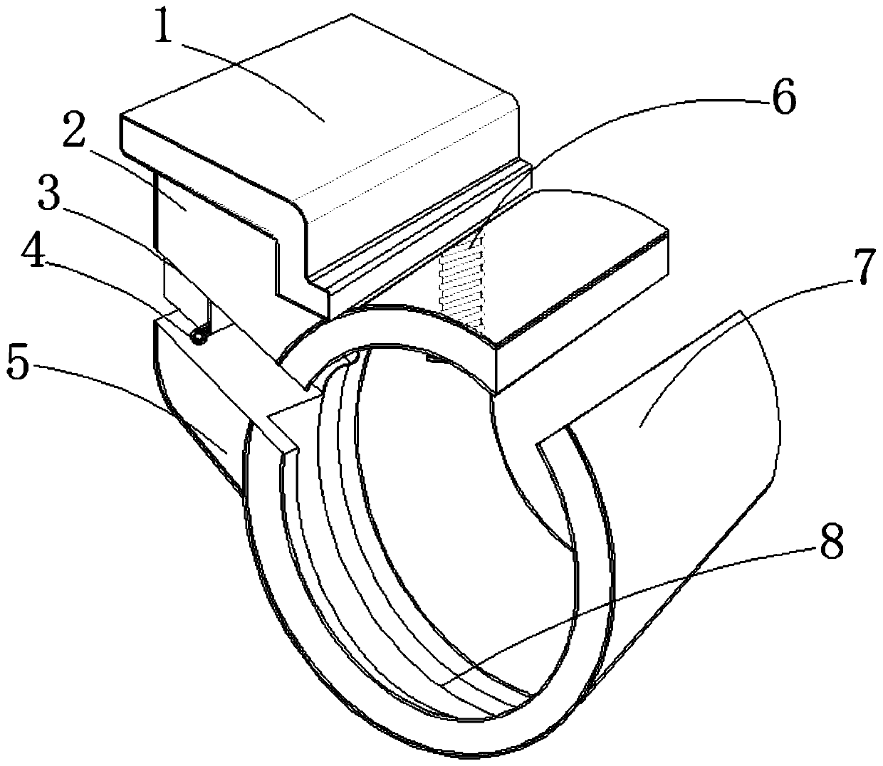
[0020] see figure 1 , a microelectronic hollow inductance winding shaft, the bottom of the upper platen 1 is elastically connected to the upper end of the extrusion block 2 through a compression spring, the outer side of the lower end of the extrusion block 2 is fixedly connected to the upper end of the fixed block 3, and the lower end of the fixed block 3 is lower left The end is fixedly connected with a blocking block 4, the inner end of the fixed block 3 is...


PUM


Abstract

The invention relates to the technical field of winding shafts, and discloses a microelectronic hollow inductor winding shaft. The side surface of an upper baffle, located on the outer ring of a rotating roller, is provided with a bayonet; the side surface middle part of the upper baffle, located at the bayonet, is provided with a clamping groove; the inner part of the clamping groove, located atthe bayonet, is fixedly connected to the inner end of a tension spring; the outer ends of the tension springs are elastically connected to the inner sides of two ends of a gear lever; an extension rodA is fixed by the gear lever, an extension rod B passes through a rotating ring and is slidably connected between two elastic support rods, the rotating roller passes through from the front surface of a casing, the extension rod A is bent and clamped between a fixing block and a supporting platform, a blocking block is buckled, a bottom baffle is clamped to the bottom end of the winding roller, the extension rod B passes through a clamping hole arranged in the bottom baffle, the bottom baffle is rotated, waste time and energy during a manual operation process can be avoided, and the efficiency in the production process is facilitated.

Description

technical field [0001] The invention relates to the technical field of bobbins, in particular to a microelectronic hollow inductance bobbin. Background technique [0002] Electromagnetic coils are used in the internal basic components of existing electrical appliances such as induction cookers and electromagnetic rice cookers. It is a structure with a spiral coil appearance. The type electromagnetic coil is fixed on the surface of the outer ring of the skeleton of the hollow bobbin, and the connection between the electromagnetic coil and the bobbin skeleton is fixed with an adhesive, and one end of the electromagnetic coil is fixed, and the operator puts the other end of the electromagnetic wire Winding on bobbin. [0003] During the winding process, one end of the electromagnetic coil needs to be fixed by manual hand support, and the middle part needs to use adhesives to help fix the electromagnetic coil in the wound part to prevent it from loosening, while the other end r...

Claims


Application Information

Patent Timeline
IPC IPC(8): H01F41/098H01F41/082
CPCH01F41/082H01F41/098
Inventor 徐坚
Owner ELECTRIC POWER RES INST OF GUANGXI POWER GRID CO LTD
Why Eureka
Try Eureka