Engine cylinder cover positioning clamp

A technology of engine cylinder head and positioning fixture, which is applied in the direction of positioning device, clamping, manufacturing tools, etc., and can solve the problems affecting the contact stiffness and mutual position accuracy of the cylinder head and the machine base assembly, and affecting the positioning accuracy of the cylinder head, etc.

Pending Publication Date: 2019-10-25
大川精工(朝阳)有限公司
View PDF9 Cites 0 Cited by
  • Summary
  • Abstract
  • Description
  • Claims
  • Application Information

AI Technical Summary

Problems solved by technology

[0003] In view of this, the present invention aims to propose a positioning fixture for the engine cylinder head, which solves the problem that in the process of processing the traditional engine cylinder head, in order to ensure the complete positioning of the engine, a variety of different fixtures are usually used to clamp the engine cylinder head at the same time. Technical issues that directly affect the positioning accuracy of the cylinder head during processing, and affect the contact stiffness and mutual position accuracy of the cylinder head and machine base during assembly

Method used

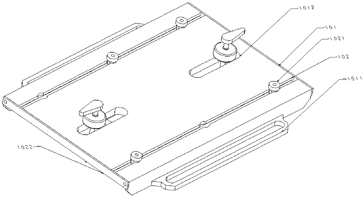
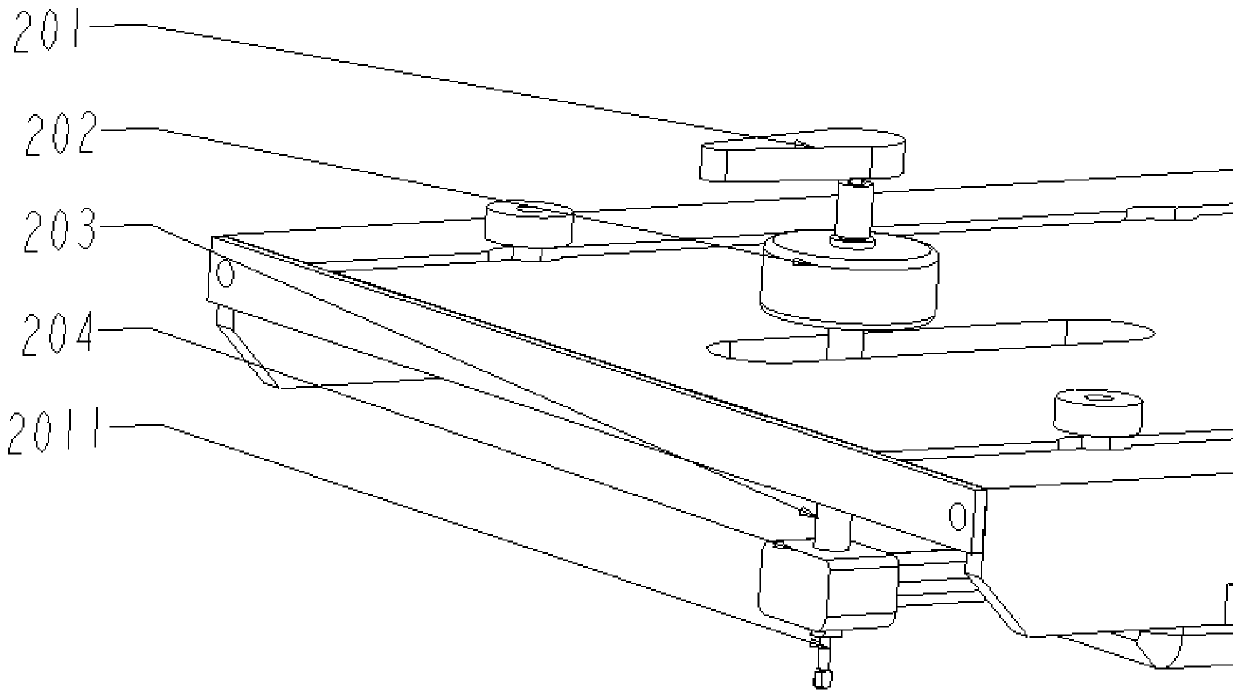
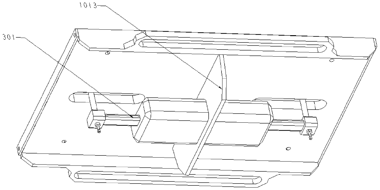

Image

  • Engine cylinder cover positioning clamp
  • Engine cylinder cover positioning clamp
  • Engine cylinder cover positioning clamp

Examples


Embodiment Construction

[0025] It should be noted that, in the case of no conflict, the embodiments of the present invention and the features in the embodiments can be combined with each other.

[0026] In describing the present invention, it should be understood that the terms "center", "longitudinal", "transverse", "upper", "lower", "front", "rear", "left", "right", " The orientations or positional relationships indicated by "vertical", "horizontal", "top", "bottom", "inner" and "outer" are based on the orientations or positional relationships shown in the drawings, and are only for the convenience of describing the present invention and Simplified descriptions, rather than indicating or implying that the device or element referred to must have a particular orientation, be constructed and operate in a particular orientation, and thus should not be construed as limiting the invention. In addition, the terms "first", "second", etc. are used for descriptive purposes only, and should not be understood ...


PUM


Abstract

The invention provides an engine cylinder cover positioning clamp. A fixing plate structure, a locking mechanism and a positioning structure are included. Long circular holes are symmetrically formedin the left side and the right side of the middle portion of the fixing plate structure. The locking mechanism comprises two drive air cylinders and two cam locking structures. Each long circular holeis internally correspondingly provided with one cam locking structure. The cam ends of the cam locking structures are arranged at the upper end of the fixing plate structure. The bottom end of each cam locking structure is correspondingly connected with the stretching-out end of one drive air cylinder. The positioning structure comprises a plurality of positioning blocks and two sliding grooves arranged in parallel, each sliding groove is internally at least provided with two positioning blocks, each positioning block is detachably connected with a positioning plate structure, and the top endof each positioning block is a smooth plane. The engine cylinder cover positioning clamp solves the technical problems that in the traditional engine cylinder cover machining process, a plurality ofdifferent clamps are usually used for clamping an engine cylinder cover at the same time, and the positioning precision during cylinder cover machining is directly influenced.

Description

technical field [0001] The invention belongs to the field of cylinder head manufacturing, and in particular relates to a positioning fixture for an engine cylinder head. Background technique [0002] The cylinder head is one of the key components of the engine. The size of the part is small, but the structure is complex, the wall is thin and uneven, and there are many processing parts, especially several planes and hole systems, which makes the processing very difficult. Among the machining surfaces of cylinder head parts, it is usually easier to guarantee the machining accuracy of the plane, but it is difficult to guarantee the machining accuracy of the support holes with higher precision requirements and the mutual position accuracy between holes and between holes and planes. The main plane of the cylinder head is the assembly datum, and it is often the positioning datum during processing. Therefore, it should have a higher flatness and a smaller roughness value. During th...

Claims


Application Information

Patent Timeline
Patent Type & Authority Applications(China)
IPC IPC(8): B23Q3/08B25B11/00
CPCB23Q3/08B25B11/00
Inventor 张海宽张新
Owner 大川精工(朝阳)有限公司
Why Eureka
Try Eureka