
Optical module

An optical module, one-sided technology, applied in the field of optical communication, can solve the problems of high content, increased volume heat density, and reduced chip performance.

Inactive Publication Date: 2019-10-25
HISENSE BROADBAND MULTIMEDIA TECH
View PDF5 Cites 2 Cited by
  • Summary
  • Abstract
  • Description
  • Claims
  • Application Information

AI Technical Summary

Problems solved by technology

At the same time, the power of the optical module continues to increase, and the thermal density of the volume continues to increase, resulting in a high temperature when the optical module is working. The performance of the temperature-sensitive electro-optic / photoelectric conversion components and chips in the optical module will be greatly reduced, and even lead to the entire optical module. not working or failing
In order to ensure the heat dissipation of the optical module, the heat conduction pad attached to the surface of the optical device is usually used to conduct the heat on the surface of the optical device. The material of the sheet is thermally conductive silicone grease, which has high content of silicone oil and strong fluidity. Silicone oil is easy to volatilize to the inside of the optical device or other edge positions, which will change the gap between the optical device and the chassis, and then cause the coupling The tolerance changes, which makes a certain optical path or multiple optical paths in the optical device deflected, resulting in a drop in optical power

Method used


Image

  • Optical module
  • Optical module
  • Optical module

Examples


Embodiment Construction

[0019] The following will clearly and completely describe the technical solutions in the embodiments of the present invention with reference to the accompanying drawings in the embodiments of the present invention. Obviously, the described embodiments are only some, not all, embodiments of the present invention. Based on the embodiments of the present invention, all other embodiments obtained by persons of ordinary skill in the art without making creative efforts belong to the protection scope of the present invention.

[0020] In the description of the present invention, it should be understood that the orientation or positional relationship indicated by the terms "upper", "lower", "vertical", "horizontal", "inner", "outer" etc. The method or positional relationship is only for the convenience of describing the present invention and simplifying the description, but does not indicate or imply that the referred device or element must have a specific orientation, be constructed a...


PUM


Abstract

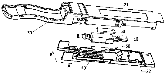
The invention provides an optical module, which comprises an optical device, a pedestal, a cover plate and a handle arranged on the pedestal, wherein the handle is arranged at the end part of the pedestal, the cover plate is connected with the pedestal in a snap fit, the optical device is arranged in an accommodating space formed by enclosing the pedestal and the cover plate, a plurality of pits,facing a recess at the inner side of the cover plate or the pedestal, are formed in the bottom surface of the cover plate or the pedestal, the plurality of pits are distributed in the cover plate or the pedestal in the form of a rectangular array, heat conductive gaskets are arranged between the pits and the optical device, one surface of each heat conductive gasket is at least adhered to the interior of the corresponding pit, the other surface of each heat conductive gasket is adhered to the surface of the optical device, and the heat conductive gaskets are partially limited in the pits, thusthe heat conductive gaskets can be limited to generating irregular diffusion and deformation to extrude the side portions of the optical device, thereby ensuring the coupling tolerance between the optical device and a casing, and ensuring the optical power of the optical module.

Description

technical field [0001] The invention relates to the technical field of optical communication, in particular to an optical module. Background technique [0002] The optical module is the core device for transmitting optical signals through optical fibers in the optical fiber network. The rate of existing modules is getting higher and higher, jumping from 25G to 200G, or even 400G. The development trend of high integration and high speed of optical communication modules makes optical modules continue to develop in the direction of multi-channel, miniaturization, and high density. At the same time, the power of the optical module continues to increase, and the thermal density of the volume continues to increase, resulting in a high temperature when the optical module is working. The performance of the temperature-sensitive electro-optic / photoelectric conversion components and chips in the optical module will be greatly reduced, and even lead to the entire optical module. Not ...

Claims


Application Information

Patent Timeline
IPC IPC(8): G02B6/42
CPCG02B6/4267G02B6/4269
Inventor 董本正崔伟潘红超司宝峰
Owner HISENSE BROADBAND MULTIMEDIA TECH
Learn More