
Light splitting device with light amplification module

An optical branching and optical amplification technology, which is applied in the coupling, optics, and optical waveguides of optical waveguides, and can solve the problems of low receiving sensitivity of optical receiving equipment, inability to remotely manage the network management platform, and weak signal optical power.

Pending Publication Date: 2018-12-07
SHANGHAI SINO TELECOM TECH
View PDF0 Cites 1 Cited by
  • Summary
  • Abstract
  • Description
  • Claims
  • Application Information

AI Technical Summary

Problems solved by technology

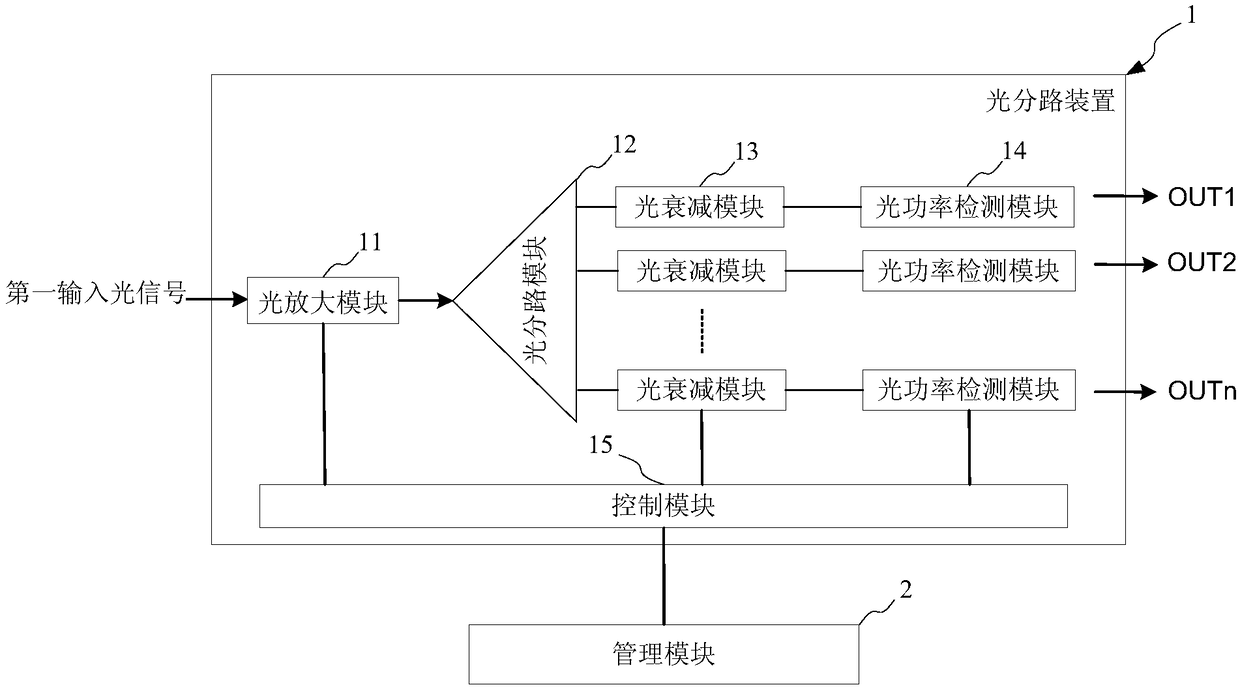
[0003] However, after the signal of the existing optical splitter is split, the optical power of the signal is very weak, which is lower than the receiving sensitivity of the back-end optical receiving equipment
In addition, the existing optical splitter is a passive device, which cannot support the configuration function of opening and closing the port, cannot realize real-time monitoring of the optical power of the port, and cannot be remotely managed through the network management platform
[0004] Therefore, how to solve the weak optical power after splitting by the optical splitter has become an urgent problem to be solved

Method used


Image

  • Light splitting device with light amplification module
  • Light splitting device with light amplification module
  • Light splitting device with light amplification module

Examples


Embodiment Construction

[0036] The implementation of the present invention will be illustrated by specific specific examples below, and those skilled in the art can easily understand other advantages and effects of the present invention from the contents disclosed in this specification.

[0037] It should be noted that the structures, proportions, sizes, etc. shown in the drawings attached to this specification are only used to match the content disclosed in the specification, for those who are familiar with this technology to understand and read, and are not used to limit the implementation of the present invention. Limiting conditions, so there is no technical substantive meaning, any modification of structure, change of proportional relationship or adjustment of size, without affecting the effect and purpose of the present invention, should still fall within the scope of the present invention. The disclosed technical content must be within the scope covered. At the same time, terms such as "upper"...


PUM


Abstract

The present invention provides a light splitting device with a light amplification module. The light division device comprises: a light amplification module configured to amplify power of first inputlight signals to form second input light signals; and a light splitting module having an input end connected with an output end of the light amplification module to receive the second input light signals. The light amplification device is connected with the light amplification module at the input end of the light splitting module to perform light power amplification of the input light signals in advance at the light splitting module so as to ensure that the light power after light splitting still can meet the receiving flexibility requirements of a rear-end receiving device, solve the problemthat a common light splitter is weak in light power after light splitting and improve the operation stability of the light splitter.

Description

technical field [0001] The invention relates to the field of photoelectric equipment, in particular to an optical branching device with an optical amplification module. Background technique [0002] Optical splitters are widely used in the field of network security. They are one of the important passive components in optical fiber links and are used to split the entire optical signal into multiple channels for transmission. [0003] However, after the signal of the existing optical splitter is split, the optical power of the signal is very weak, which is lower than the receiving sensitivity of the back-end optical receiving equipment. In addition, the existing optical splitter is a passive device, which cannot support the configuration function of opening and closing the port, cannot realize real-time monitoring of the optical power of the port, and cannot be remotely managed through the network management platform. [0004] Therefore, how to solve the weak optical power af...

Claims


Application Information

Patent Timeline
Patent Type & Authority Applications(China)
IPC IPC(8): H04B10/293H04B10/079G02B6/42G02B6/26
CPCH04B10/07955H04B10/293G02B6/266G02B6/4286
Inventor 方权揭德锋庄云飞谢虎吴志远
Owner SHANGHAI SINO TELECOM TECH
Learn More