Coupling method of light emitter and light emitter

A technology of optical transmitter and laser array, which is applied in the field of optical communication, can solve problems such as difficult repair, difficult coupling, and optical power drop, and achieves the effects of saving coupling time, reducing coupling difficulty, and reducing production costs

Inactive Publication Date: 2020-06-05
HISENSE BROADBAND MULTIMEDIA TECH
View PDF7 Cites 0 Cited by
  • Summary
  • Abstract
  • Description
  • Claims
  • Application Information

AI Technical Summary

Problems solved by technology

[0004] With regard to the above-mentioned existing assembly method of the optical transmitter, the inventors of the present invention found that: in the prior art, after the laser, the optical multiplexing component and the collimator lens are fixed, the optical fiber adapter is coupled and fixed in an active way , so during the fixing process or in the later use, once a small deformation occurs, the optical power will drop, so there is a problem of difficult coupling
In addition, since the 4-way collimator lens is fixed first, and then the fiber optic adapter is welded, when the optical power of the product fails, the adapter needs to be removed and re-coupled, making it difficult to repair

Method used


Image

  • Coupling method of light emitter and light emitter
  • Coupling method of light emitter and light emitter
  • Coupling method of light emitter and light emitter

Examples


Embodiment Construction

[0017] Embodiments of the present invention will be described below in conjunction with the accompanying drawings. The invention is applied to the production assembly of light emitters.

[0018] First, the structure of the optical transmitter provided by the embodiment of the present invention is introduced:

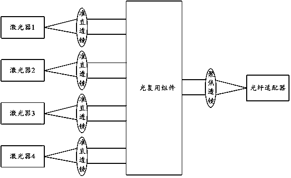
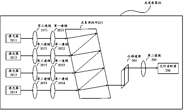
[0019] The optical transmitter provided by the embodiment of the present invention includes: N lasers, N first lenses, optical multiplexing components, displacement prisms, second lenses, and fiber optic adapters, where N≥2; wherein, the N first lenses are respectively arranged in The outgoing light paths of the N lasers are used to adjust the light beams emitted by the N lasers into collimated light; the optical multiplexing component is arranged on the outgoing light paths of the N first lenses, and is used to combine the outgoing light beams of the N first lenses Synthesize one beam; the shifting prism is set on the outgoing light path of the optical multiplexing com...


PUM


Abstract

The embodiment of the invention provides a coupling method of a light emitter and the light emitter, and relates to the technical field of optical communication. According to the embodiment of the invention, the coupling process of the light emitter can be simplified, coupling time is saved, and production cost is reduced. The method comprises the following steps: fixing N lasers, an optical multiplexing assembly and a displacement prism at preset positions; when a first laser in the N lasers is in a light emitting state, coupling and fixing a first lens corresponding to the first laser; fixing the second lens at a preset position; when the first laser is in a light-emitting state, coupling and fixing the optical fiber adapter; and respectively coupling and fixing the N-1 first lenses respectively corresponding to the N-1 lasers according to the optical power received by the optical fiber adapter in the light emitting states of the N-1 lasers except the first laser. The invention is applied to the production and assembly of the light emitter.

Description

[0001] This application is a divisional application with an application date of November 01, 2018, an application number of 201811294549.0, and a patent name of a coupling method for an optical transmitter and an optical transmitter. technical field [0002] The invention relates to the technical field of optical communication, in particular to a coupling method of an optical transmitter and the optical transmitter. Background technique [0003] In the field of high-speed data communication, the technology of micro-optics assembly is more and more widely used. figure 1 Shown is a schematic diagram of the structure of a typical multiplexed optical transmitter. The optical transmitter mainly includes 4 lasers, 4 point-to-point lenses, 4 collimating lenses, an optical multiplexing component that synthesizes 4 channels of light into 1 channel of light, a focusing lens, and an optical fiber adapter. The 4 lasers can respectively emit Lasers of different wavelengths. The basic w...

Claims


Application Information

Patent Timeline
Patent Type & Authority Applications(China)
IPC IPC(8): G02B6/42
CPCG02B6/4206G02B6/4214G02B6/4296
Inventor 李丹杜光超唐永正傅钦豪
Owner HISENSE BROADBAND MULTIMEDIA TECH
Why Eureka
Try Eureka