A dimming method and device for automatic coupling of optical switches

An automatic coupling and optical switch technology, applied in the field of optical communication, can solve the problems of amplitude dependence, poor repeatability, and difficulty in large-scale production of rotating fine-tuning handwheels, so as to reduce the difficulty of coupling and labor costs, realize rapid automatic debugging, realize The effect of mass production

Active Publication Date: 2020-07-31
GUANGXUN SCI & TECH WUHAN
View PDF3 Cites 0 Cited by
  • Summary
  • Abstract
  • Description
  • Claims
  • Application Information

AI Technical Summary

Problems solved by technology

However, this manual coupling debugging method has low production efficiency, high production cost, poor repeatability, poor consistency, poor alignment accuracy, low yield rate, and is difficult to scale production, and the range of rotating the fine-tuning handwheel depends on the experience of the debugging staff and cannot Quantify

Method used


Image

  • A dimming method and device for automatic coupling of optical switches
  • A dimming method and device for automatic coupling of optical switches
  • A dimming method and device for automatic coupling of optical switches

Examples


Embodiment 1

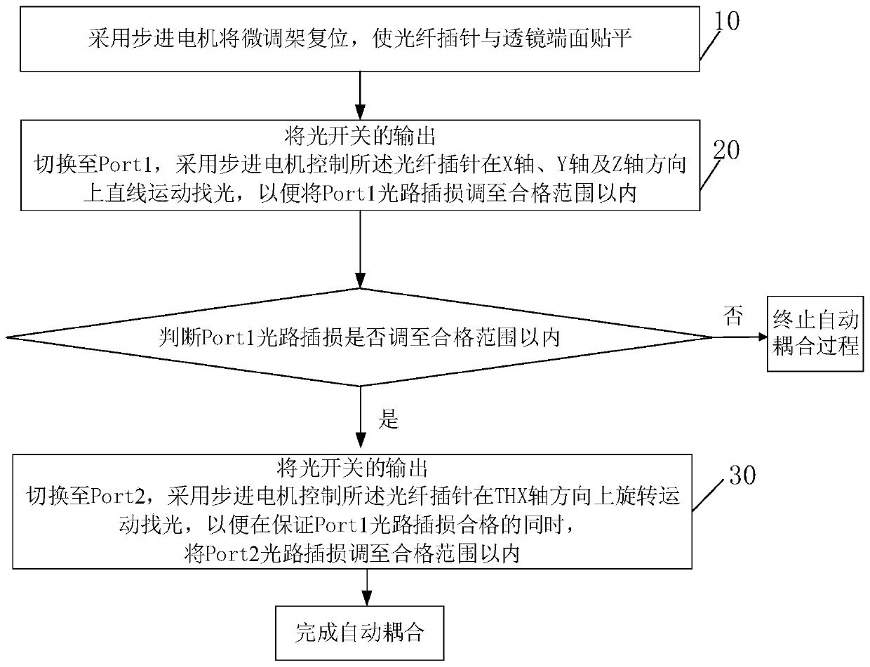
[0054] An embodiment of the present invention provides a dimming method for automatic coupling of optical switches, such as figure 1 shown, including the following steps:

[0055] Step 10, use the stepper motor to reset the fine-tuning frame, so that the optical fiber ferrule and the end surface of the lens are flattened.

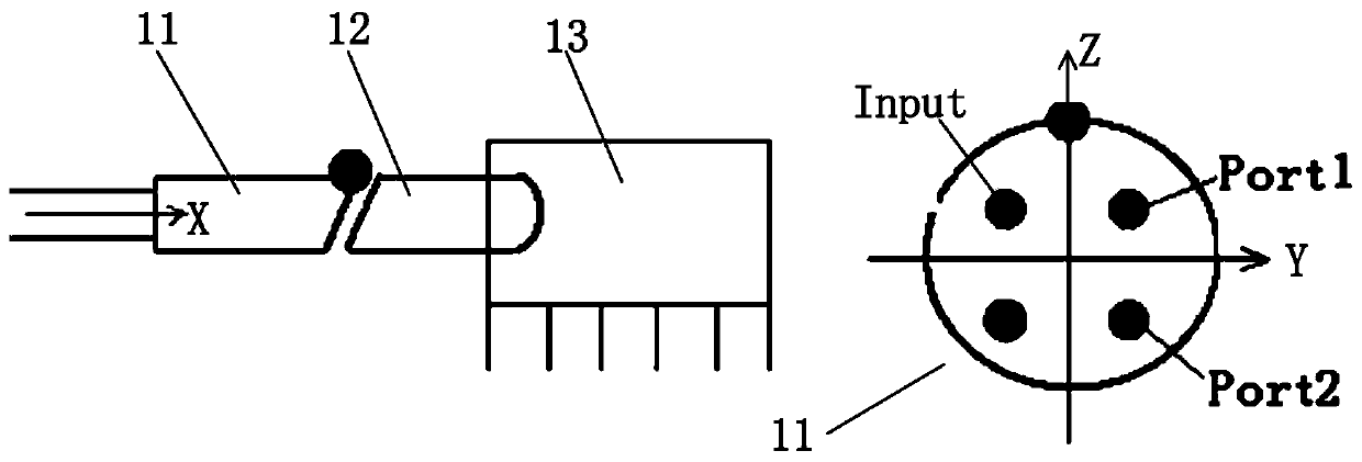
[0056] In the embodiment of the present invention, the optical switch used is a 1×2 mechanical optical switch, refer to figure 2 , where the left figure is the front view of the optical switch, the optical switch includes a fiber optic ferrule 11, a C-Lens lens 12 and a switch box housing 13, in order to avoid the influence of reflected light on communication, the end face of the optical fiber ferrule 11 The end face is inclined at 8 degrees. The C-Lens lens 12 is used to collimate the light beam. The switch box housing 13 is also provided with a reflector. The optical signal enters from the left side through the optical fiber pin 11 and passes After the...

Embodiment 2

[0079] On the basis of the above-mentioned embodiment 1, this embodiment of the present invention also provides a dimming method for automatic coupling of an optical switch. Mismatch steps are applicable to the situation where the insertion loss of Port1 and Port2 optical paths cannot be adjusted to the acceptable range at the same time after step 10-step 30. By adding this step, the axial and / or radial mismatch can be further eliminated , to improve the debugging accuracy.

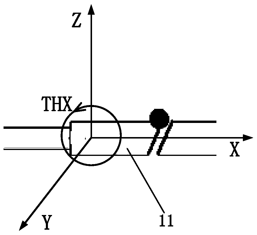
[0080] In an optical passive device whose pigtail is a single-mode fiber, the beam can be treated by Gaussian approximation, and the coupling loss of the device can be analyzed by the coupling efficiency between Gaussian beams, and the coupling between two Gaussian beams generally has three kinds of losses Matching mode: axial X axis mismatch, radial Y, Z axis mismatch and angular THX axis mismatch, refer to Figure 8 , if only axial mismatch exists, then X 0 ≠0,Z 0 =0, θ=0; if there is only a radial m...

Embodiment 3

[0095] On the basis of the dimming method for automatic coupling of optical switches provided in Embodiment 1 and Embodiment 2, the present invention also provides a device for automatic coupling and dimming of optical switches using the above method, such as Figure 11 Shown is a schematic diagram of the device architecture of the embodiment of the present invention. The dimming device for automatic coupling of optical switches in this embodiment includes one or more processors 21 and memory 22 . in, Figure 11 A processor 21 is taken as an example.

[0096] The processor 21 and the memory 22 may be connected via a bus or in other ways, Figure 11 Take connection via bus as an example.

[0097] The device also includes two photodetectors, which are used to monitor the real-time optical path insertion loss of the optical switches Port1 and Port2 and feed back to the processor 21 for processing.

[0098] The memory 22 is a non-volatile computer-readable storage medium for t...


PUM


Abstract

The invention relates to the field of optical communication, and relates to a dimming method and a dimming device for automatic coupling of an optical switch. The dimming method includes: resetting afine adjusting frame to enable an optical fiber base pin to be close to and parallel to a lens end face; switching to Port 1, controlling the optical fiber base pin to move rectilinearly on an X axis,a Y axis and a Z axis to search light, and adjusting insertion loss of a Port 1 optical path in a qualified limit; switching to Port 2, controlling the optical fiber base pin to rotate in on a T axis, an H axis and the X axis to search light, and adjusting insertion loss of a Port 2 optical path in a qualified limit while the insertion loss of the Port 1 optical path is qualified. According to optical path characteristics of the optical switch and optical path coupling characteristics, movement rules of the optical fiber base pin is quantified and used for controlling a stepping motor, the optical fiber base pin is driven to move, automatic aligning and debugging between the optical fiber base pin and a lens are realized, coupling difficulty is lowered, labor cost is reduced, debugging efficiency, repeatability, consistency and accuracy are improved, and large-scale production can be realized.

Description

【Technical field】 [0001] The invention relates to the field of optical communication, in particular to a dimming method and device for automatic coupling of optical switches. 【Background technique】 [0002] In recent years, IP-based Internet services have shown explosive growth. This growth trend has not only changed the relationship between the IP network layer and the underlying transmission network, but also brought new challenges to the networking mode, node design, management and control of the entire network. requirements. In this case, an intelligent network architecture—Automatic Switched Optical Networks (ASON for short) has become a hotspot in system research today, and its core nodes are composed of optical cross-connects (Optical Cross-connect It is composed of OXC) equipment, through which dynamic wavelength routing and flexible and effective management of optical networks can be realized, and the optical switch, as a functional device for switching optical pat...

Claims


Application Information

Patent Timeline
Patent Type & Authority Patents(China)
IPC IPC(8): G02B6/42
CPCG02B6/4225G02B6/4227
Inventor 杨波谭书伟龚垒
Owner GUANGXUN SCI & TECH WUHAN
Why Eureka
Try Eureka