Installation device and installation method

A technology of an installation device and an installation method, applied in the directions of electrical components, electrical components, etc., can solve the problems of positional deviation, difficult-to-insert parts, protruding insertion, etc.

Active Publication Date: 2019-10-25
JUKI CORP
View PDF26 Cites 0 Cited by
  • Summary
  • Abstract
  • Description
  • Claims
  • Application Information

AI Technical Summary

Problems solved by technology

[0004]However, when a plurality of types of protrusions are provided on the insertion member, if one type of protrusion is aligned with the reference, other types of protrusions will be aligned. Position deviation occurs at the protrusion, making it difficult to insert each protrusion of the insertion part into each through hole of the substrate

Method used


Image

  • Installation device and installation method
  • Installation device and installation method
  • Installation device and installation method

Examples


Embodiment Construction

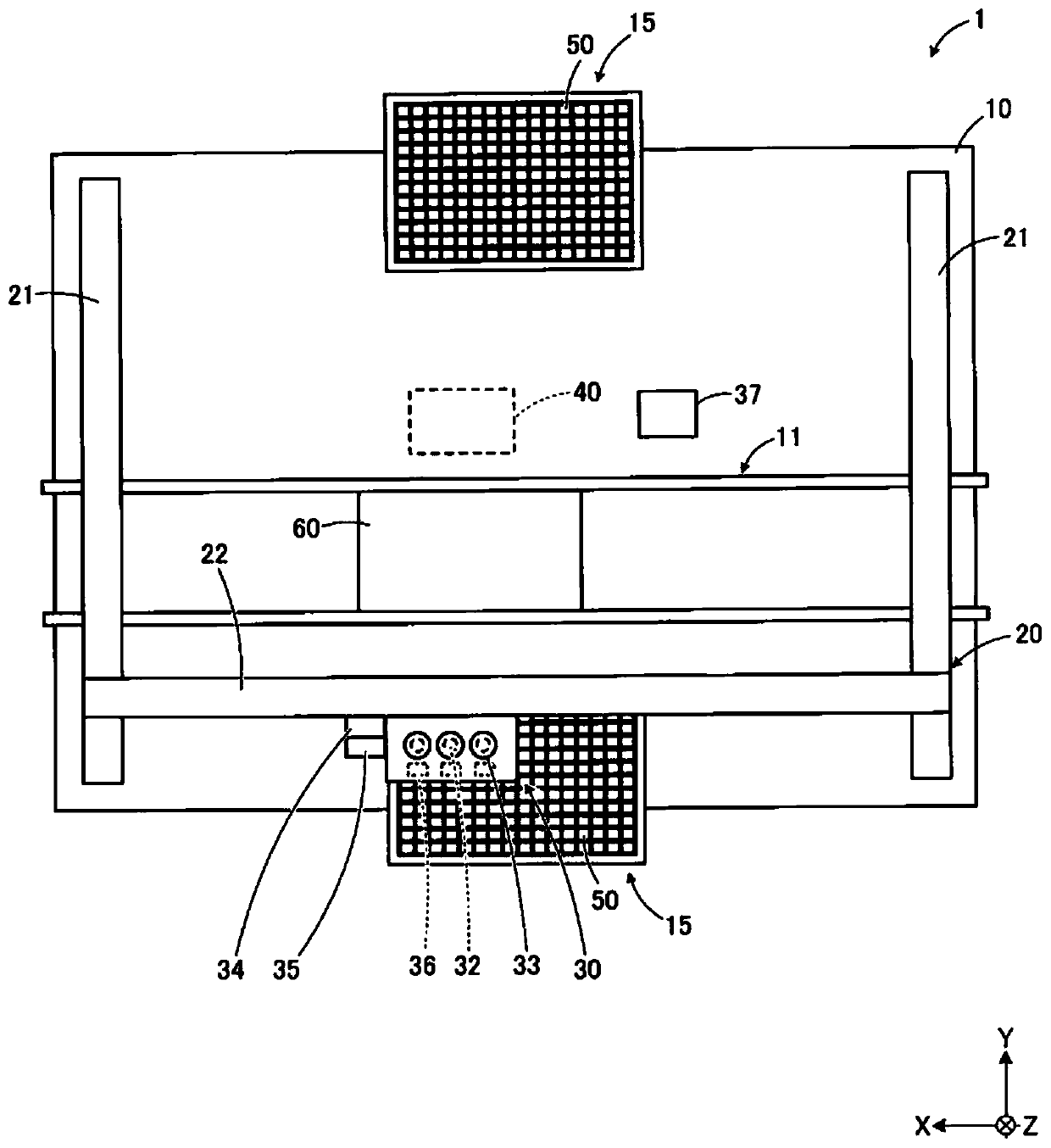
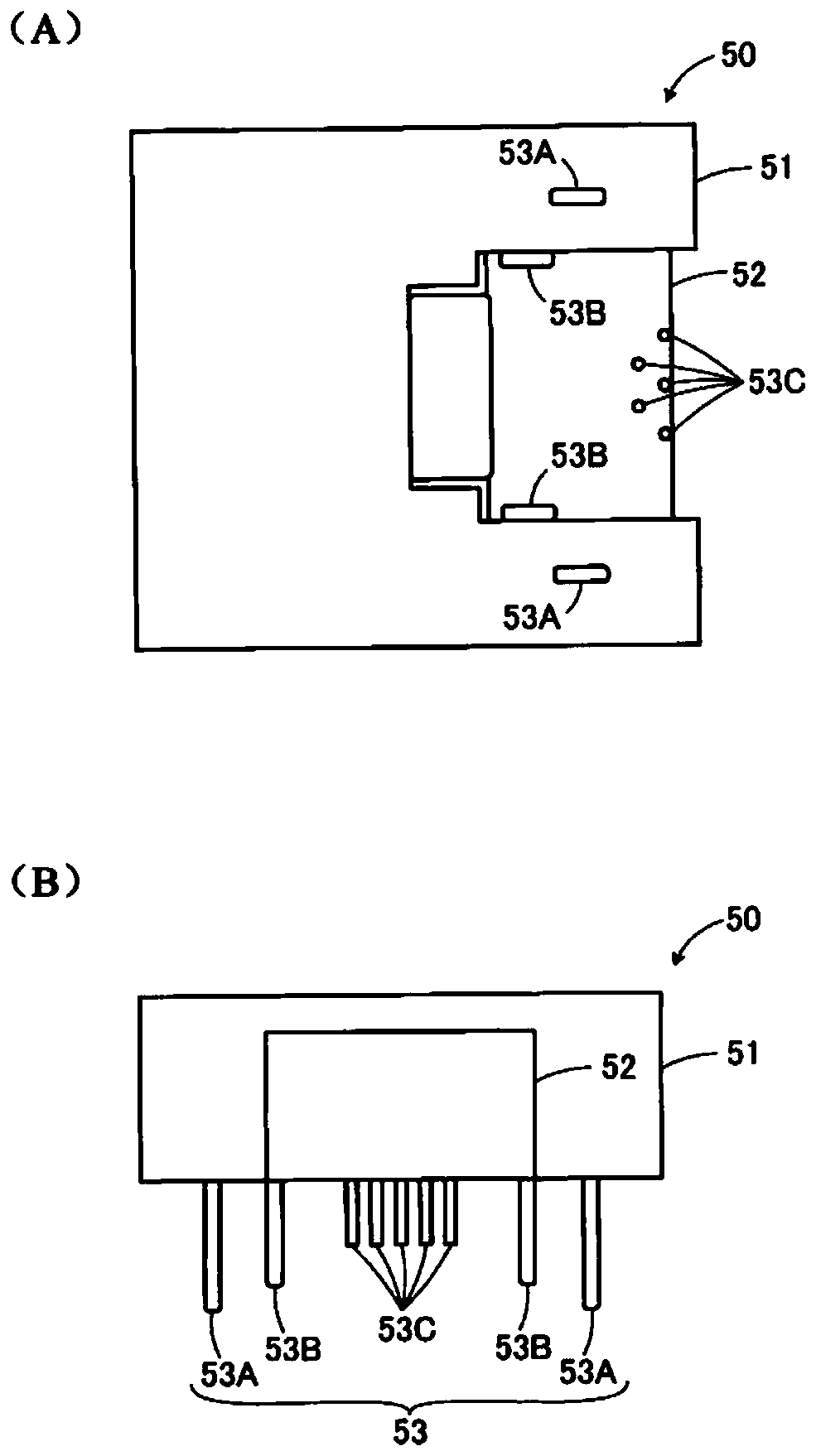
[0036] Next, a mounting device having an image processing device according to the present embodiment will be described with reference to the drawings. figure 1 It is a schematic plan view of the mounting device of this embodiment. In addition, the attachment device of this embodiment is just an example, and can be changed suitably. figure 2 It is a schematic diagram of the insertion member of this embodiment.

[0037] like figure 1 As shown, the mounting device 1 is configured to pick up the insertion component 50 from the component supply device 15 by the mounting head 30 and mount it at a predetermined position on the substrate 60 . A substrate transfer unit 11 for transferring a substrate 60 in the X-axis direction is arranged substantially at the center of the base 10 of the mounting apparatus 1 . The substrate transport unit 11 carries and positions the substrate 60 before component mounting to the lower side of the mounting head 30 from one end side in the X-axis dir...


PUM


Abstract

The present invention provides an installation device and an installation method for appropriately intalling an insertion member provided with a plurality of types of projections on a substrate. The installation device holds an insertion member (50) provided with a plurality of types of protrusions (53A, 53B, 53C) having different lengths by using a suction nozzle (32). The protrusions are inserted into through holes (61) of the substrate (60) so that the insertion member is installed on the substrate. The installation device is configured to control the suction nozzle so as to obtain the position information of the tips of at least two types of protrusions among the plurality of types of protrusions. Position correction is performed for each type of the protrusions in turn from the long one of the at least two types of protrusions based on the position information of the tip of each protrusion, and the tip of the protrusion is inserted into the through hole of the substrate.

Description

technical field [0001] The present disclosure relates to a mounting device and a mounting method. Background technique [0002] As a mounting device, there is known a mounting device for mounting an interposer on a substrate by inserting a protrusion such as a lead terminal or a boss of the interposer into a through hole of the substrate (for example, refer to Patent Document 1). In the mounting device described in Patent Document 1, an insertion member is picked up by a suction nozzle, and positions of a plurality of projections protruding from the insertion member are recognized by an imaging device. Then, the insertion member is conveyed directly above the plurality of through holes formed in the substrate, and the insertion member is vertically lowered toward the through holes of the substrate, thereby inserting each protrusion of the insertion member straightly into each through hole of the substrate. [0003] Patent Document 1: Japanese Patent Laid-Open No. 62-143497 ...

Claims


Application Information

Patent Timeline
Patent Type & Authority Applications(China)
IPC IPC(8): H05K13/04
CPCH05K13/0408
Inventor 儿玉裕介石桥慎太郎佐佐木孝一郎
Owner JUKI CORP
Why Eureka
Try Eureka