Supercharge Your Innovation With Domain-Expert AI Agents!

Resonance damping element and power converter with resonance damping element

A technology of power converters and damping elements, applied in the field of resonance damping elements, can solve problems such as overcurrent tripping, burning out of protective fuses, etc.

Active Publication Date: 2022-02-01
伟肯有限公司
View PDF3 Cites 0 Cited by
  • Summary
  • Abstract
  • Description
  • Claims
  • Application Information

AI Technical Summary

Problems solved by technology

Resonant currents can cause unwanted overcurrent trips or burn out protective fuses

Method used


Image

  • Resonance damping element and power converter with resonance damping element
  • Resonance damping element and power converter with resonance damping element
  • Resonance damping element and power converter with resonance damping element

Examples


Embodiment Construction

[0038] Exemplary embodiments of the present disclosure will hereinafter be described in detail with reference to the accompanying drawings, wherein like reference numerals designate like elements. This disclosure may, however, be embodied in many different forms and should not be construed as limited to the embodiments set forth herein; rather, these embodiments are provided so that this disclosure will be thorough and complete, and will address the needs of those skilled in the art skilled person to fully convey the concepts of the disclosure.

[0039] In the following detailed description, for purposes of explanation, numerous specific details are set forth in order to provide a thorough understanding of the disclosed embodiments. It will be apparent, however, that one or more embodiments may be practiced without these specific details. In other instances, well-known structures and devices are shown schematically in order to simplify the drawings.

[0040] According to the...


PUM

PropertyMeasurementUnit
Resonant frequencyaaaaaaaaaa

Abstract

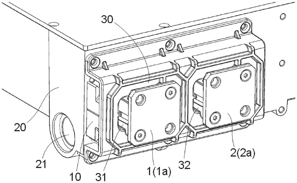
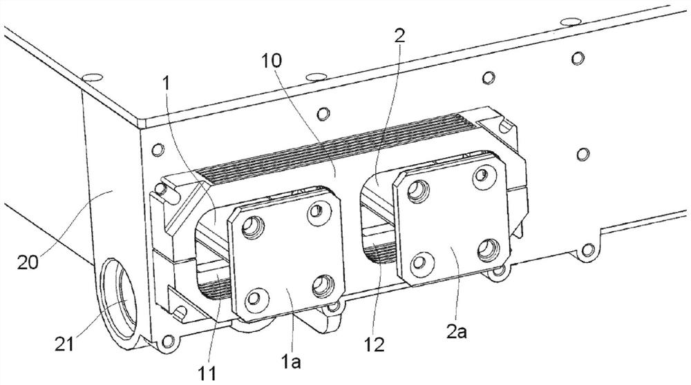
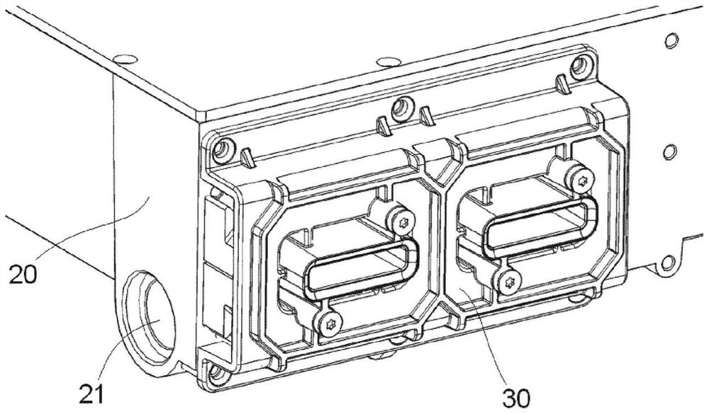
A resonance damping element (10) for a power converter having a positive busbar (1) and a negative busbar (2), wherein the resonance damping element (10) comprises a magnetic core formed with two openings ( 11, 12), the positive busbar (1) and the negative busbar (2) of the power converter respectively pass through these two openings for wiring.

Description

technical field [0001] The present invention relates to a resonance damping element for a power converter and a power converter with the resonance damping element. Background technique [0002] The problem addressed by the invention is the resonant current between the converter DC link when a rectifier (passive or active) is coupled with a motor inverter unit. Capacitors, such as film capacitors or electrolytic capacitors, are commonly used as DC link energy storage devices in power converter DC links. Although the ESR (equivalent series resistance) value in film capacitors is usually much lower than in electrolytic capacitors, when using film capacitors as a DC link energy storage device in a power converter DC link, there will be a difference between the two An underdamped LC circuit is formed between the converters. Such an underdamped LC circuit will resonate at a frequency which can be close to the switching frequency of the power converter. Therefore, large AC curre...

Claims


Application Information

Patent Timeline
Patent Type & Authority Patents(China)
IPC IPC(8): H02M1/14H02M7/00H01F27/26H01F27/38H01F27/34
CPCH01F27/266H02M1/14H02M7/003H01F27/10H01F27/245H01F27/255H01F2017/067H01F27/085H01F27/263
Inventor 马尔科·科斯凯拉尤卡·林纳韦萨·瓦萨宁
Owner 伟肯有限公司
Features
  • R&D
  • Intellectual Property
  • Life Sciences
  • Materials
  • Tech Scout
  • Unparalleled Data Quality
  • Higher Quality Content
  • 60% Fewer Hallucinations
Learn More