
Device for correcting scoliosis posture

A protruding and posture technology, applied in the field of scoliosis posture correction devices, can solve problems such as stiff spine, large sequelae, pain, etc., and achieve good correction effect, improve correction effect, and use flexible effects.

Active Publication Date: 2019-10-29
THE AFFILIATED HOSPITAL OF SHANDONG UNIV OF TCM
View PDF4 Cites 1 Cited by
  • Summary
  • Abstract
  • Description
  • Claims
  • Application Information

AI Technical Summary

Problems solved by technology

[0006] However, in the technical solutions for correcting spinal deformation in the above-mentioned prior art, devices or methods such as post-event traction are mainly used, and the correction process is relatively painful; if bracket therapy or surgical treatment is used, the risk of surgical treatment is high, leaving various sequelae The possibility is also relatively high, and it is a stiff spine in exchange for a movable deformed spine, leaving a large scar that cannot be removed for life, leaving a lifetime of pain and regret for the patient

Method used


Image

  • Device for correcting scoliosis posture
  • Device for correcting scoliosis posture
  • Device for correcting scoliosis posture

Examples


Embodiment 1

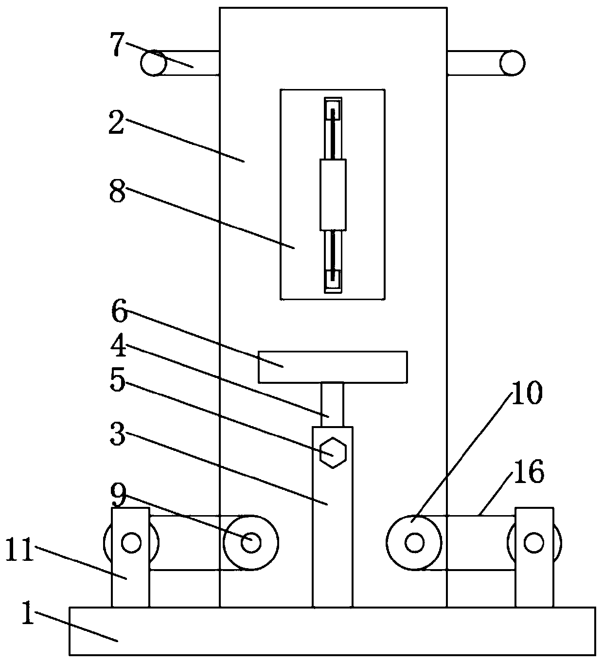
[0055] According to Figure 1-5 As shown, a scoliosis posture correction device includes a base 1 and a support plate 2. The bottom of the support plate 2 is fixedly connected to the rear side of the base 1, and the top of the base 1 is fixedly installed in the middle The support cylinder 3 has an inner liner rod 4 inserted into the support cylinder 3, the liner rod 4 is fixed to the support cylinder 3 by an adjusting bolt 5, and a seat body 6 is fixedly installed at the top of the inner liner rod 4, The inner liner rod 4 can be drawn outward and fixed by the adjusting bolt 5 according to the needs of use, thereby adjusting the height of the seat body 6.

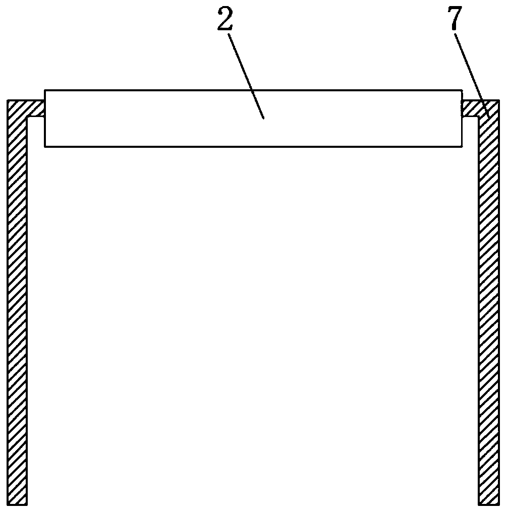
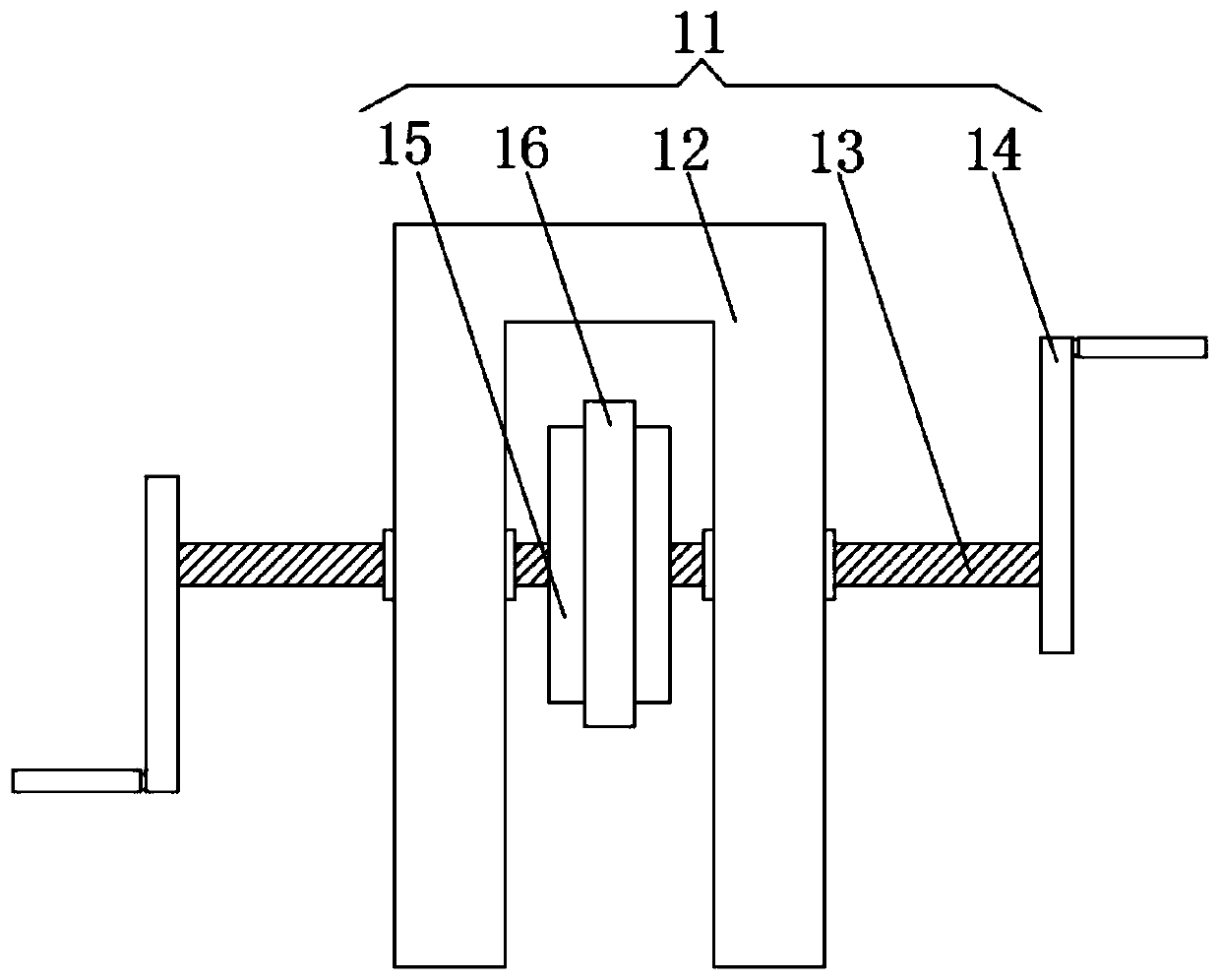
[0056] Both the left and right sides of the support plate 2 are fixedly connected with grip rods 7 for the user to hold. When the user grips the grip rod 7, the user's shoulders will not shake during the correction process. An adjustment plate 8 is fixedly installed on the front of the support plate 2, and a symmetrically arra...

Embodiment 2

[0068] A posture correction device for scoliosis, comprising a base 1 and a support plate 2. The bottom of the support plate 2 is fixedly connected to the rear side of the base 1, and a support tube 3 is fixedly installed at the top of the base 1 , The inner liner rod 4 is inserted into the support cylinder 3, the liner rod 4 is fixed to the support cylinder 3 by the adjusting bolt 5, the top of the liner rod 4 is fixedly installed with a seat body 6, which can be used according to If necessary, the inner lining rod 4 is drawn outward and fixed by the adjusting bolt 5 to adjust the height of the seat body 6.

[0069] Both the left and right sides of the support plate 2 are fixedly connected with grip rods 7 for the user to hold. When the user grips the grip rod 7, the user's shoulders will not shake during the correction process. An adjustment plate 8 is fixedly installed on the front of the support plate 2, and a symmetrically arranged first rotating shaft 9 is movably installed...


PUM


Abstract

The invention discloses a device for correcting scoliosis posture. The device comprises a base and a supporting plate, wherein the bottom of the supporting plate is fixedly connected to the rear sideof the base; a supporting cylinder is fixedly arranged in the middle of the top of the base; an inner lining rod is inserted into the supporting cylinder; holding rods are fixedly connected to the left side and the right side of the supporting plate; and an adjusting plate is fixedly arranged on the front side of the supporting plate. The device drives a jacking block to jack up or reset in a pedal mode so as to achieve the purpose of correcting scoliosis, has a good correction effect, can exercise legs while correcting, can adjust the height of the seat body according to use requirements, canmeet the requirement of correcting and treating left and right scoliosis by changing the sitting posture orientation, and is more flexible to use.

Description

Technical field [0001] The invention belongs to the technical field related to scoliosis correction, and particularly relates to a scoliosis posture correction device. Background technique [0002] Scoliosis is commonly known as scoliosis. The spine of a normal person should be a straight line viewed from the back, that is, the coronal plane, and the trunk should be symmetrical on both sides. X-rays show that the spine has lateral curvature, which can be diagnosed as scoliosis. Scoliosis can affect the normal growth and development of the patient's bones, while scoliosis can deform the patient's body. In severe cases, it can also affect cardiopulmonary function, even involving the spinal cord, causing paralysis. [0003] In order to treat spinal deformation, the following technical solutions are often used in the prior art: [0004] Chinese patent application 201320195354.7 discloses a traction device for visualizing spine deformity without weight traction, which includes a suspensi...

Claims


Application Information

Patent Timeline
Patent Type & Authority Applications(China)
IPC IPC(8): A61H1/00A61H1/02
CPCA61H1/008A61H1/0292A61H2205/081
Inventor 辛健甘召华
Owner THE AFFILIATED HOSPITAL OF SHANDONG UNIV OF TCM
Learn More