Wire tightening device for electric wires

A wire-tightening and wire-tightening technology is applied in the field of wire-tightening devices, which can solve the problems of easy knotting of wires, reduce safety, waste resources, etc., and achieve the effects of improving convenience, reducing labor intensity, and improving work efficiency.

Active Publication Date: 2019-10-29
京开能源有限公司
View PDF7 Cites 4 Cited by
  • Summary
  • Abstract
  • Description
  • Claims
  • Application Information

AI Technical Summary

Problems solved by technology

[0002] The wire is composed of one or several soft wires, covered with a light and soft sheath. The wires are wound in circles for the convenience of use and portability, and then bundled with tape, but when you need to use it, open the tape Finally, due to the elasticity of the wire itself, and the bundled wires lose the limiting tape, they are easy to scatter, and it is inconvenient to bundle again, and the wires are easy to knot when they are used next time, which brings inconvenience to users. Generally, it consists of three parts: core wire, insulating sheath and protective sheath. For the current wire fastening device, because its structure is too simple, it often breaks when it is used later. At the same time, it is easier to fasten. It is very troublesome to dismantle, most of them are disposable, wasting resources
[0003] A new type of wire tightening device for distribution lines, publication number: CN206237057U. This utility model has a single structure and function. When tightening the wires, it cannot achieve double tightening of the wires, which reduces the safety during the tightening process. resistance, and it is easy to cause the wire to fall off

Method used


Image

  • Wire tightening device for electric wires
  • Wire tightening device for electric wires
  • Wire tightening device for electric wires

Examples


Embodiment

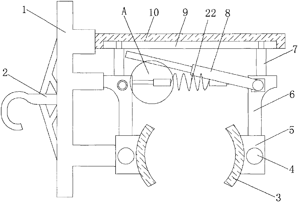
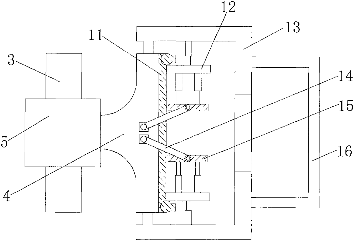
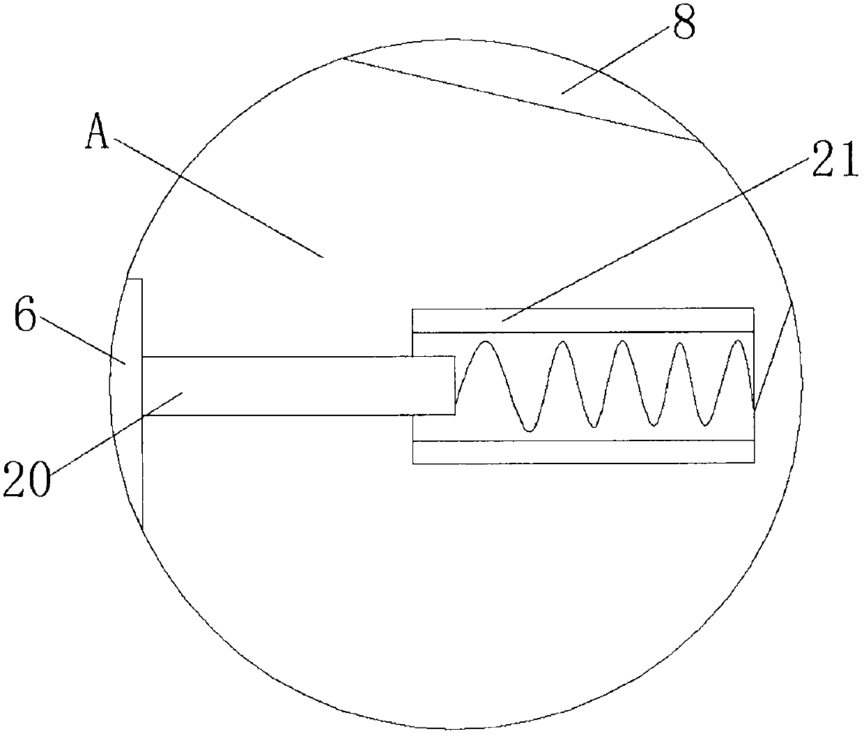
[0023] Example: refer to Figure 1-4 , a wire tightening device for electric wires. Before starting to tighten the wires, the first stop bar 8 is first removed from the locking frame 6 close to the fixed frame 1, so that the two movable blocks 20 are in the first spring 17 and the second spring 22 have elastic action at the same time, so that when the first spring 17 and the second spring 22 are stretching, the distance between the movable block 20 is pushed to increase, and then the locking frame 6 and the sliding rod 7 are linked , do a horizontal linear movement along the sliding groove 9, at the same time the distance between the two first clamping plates 3 can be increased, and then the push rod that is fixedly connected between the support frame 13 and the sliding plate 12 can be adjusted to push The rod is compressed to reduce the distance of the push rod, so that the movement of the push rod drives the sliding plate 12 to move along the slide rail 11. After the spring ...


PUM


Abstract

The invention discloses a wire tightening device for electric wires. The wire tightening device for the electric wires comprises a fixing frame, a positioning hook is welded to the side wall of one end of the fixing frame, a connecting plate is welded to the side wall of the other end of the fixing frame, a sliding groove is formed in the side wall of the connecting plate, a sliding rod is connected to the side wall of the sliding groove in a sliding mode, one end of the sliding rod is fixedly connected with a locking frame, a movable block is fixedly connected to the side wall of the lockingframe, a first spring is welded to the side wall of the movable block, the first spring is placed in a fixing shell, the side wall of the bottom end of the locking frame is fixedly connected with fixing plates through studs, and first clamping plates are fixedly connected to the side walls of one ends of the fixing plates. The locking frame far away from one side of the fixing frame can be manually pushed to enable the locking frame to drive the sliding rod at the upper end to move along the sliding groove, through movement of first clamping plates at the lower end and compression of a first spring and a second spring, a first limiting rod is fixedly clamped in the locking frame to complete the wire fixation of the first clamping plates.

Description

technical field [0001] The invention relates to the technical field of electrical engineering, in particular to a wire tightening device for electric wires. Background technique [0002] The wire is composed of one or several soft wires, covered with a light and soft sheath. The wires are wound in circles for the convenience of use and portability, and then bundled with tape, but when you need to use it, open the tape Finally, due to the elasticity of the wire itself, and the bundled wires lose the limiting tape, they are easy to scatter, and it is inconvenient to bundle again, and the wires are easy to knot when they are used next time, which brings inconvenience to users. Generally, it consists of three parts: core wire, insulating sheath and protective sheath. For the current wire fastening device, because its structure is too simple, it often breaks when it is used later. At the same time, it is easier to fasten. It is very troublesome to dismantle, and most of them are...

Claims


Application Information

Patent Timeline
Patent Type & Authority Applications(China)
IPC IPC(8): B65B13/20B65B13/18B65B27/06
CPCB65B13/18B65B13/20B65B27/06
Inventor 王俊虎
Owner 京开能源有限公司
Why Eureka
Try Eureka