Cable-forming machine by utilizing centrifugal adjustment tension

A cable forming machine and tension technology, which is applied in the direction of cable/conductor manufacturing, electrical components, circuits, etc., can solve problems such as different cable tension, waste wire, and insufficient cable consideration, so as to ensure constant tension, improve processing quality, Avoid the Serpentine Bending Effect

Active Publication Date: 2019-10-29
诸暨市友利针纺织有限公司
View PDF7 Cites 3 Cited by
  • Summary
  • Abstract
  • Description
  • Claims
  • Application Information

AI Technical Summary

Problems solved by technology

[0002] With the rapid development of China's electric power construction, the wire and cable industry has developed rapidly, and its demand continues to grow. Cable production is to draw different cables to the twisted cage and then twist them. After twisting, they wrap the outer surface. Different The cable is not well considered in the process of being drawn to the twisted cage, and has the following disadvantages: 1. During the cable processing process, cables of different types are usually placed on the cradle for transportation. In order to ensure the same tension between the cables, gears are usually used to The meshing drives each cable reel to rotate at the same speed and output the cable, but at the same speed, the remaining length of the cable in different cable reels is different, and the diameter of the cable reel is also different. The larger diameter cable reel The length of the output cable is greater than the length of the cable output by the smaller diameter cable drum, resulting in different tensions of the two output cables, and the two cables have different winding lengths when twisted. The core with greater tension is stretched and the tension is higher The small wire core is squeezed, which causes the stranded cable to arch and eventually form a serpentine bend; 2. At the same time, during the cable stranding process, the friction between the outer surfaces of the cables causes the different angles of torsion to cause the cable to arch And form a snake wire cable, eventually produce waste wire

Method used


Image

  • Cable-forming machine by utilizing centrifugal adjustment tension
  • Cable-forming machine by utilizing centrifugal adjustment tension
  • Cable-forming machine by utilizing centrifugal adjustment tension

Examples


Embodiment

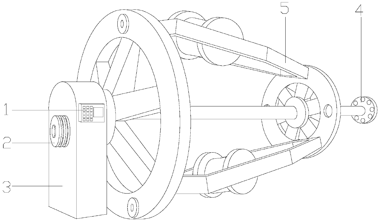
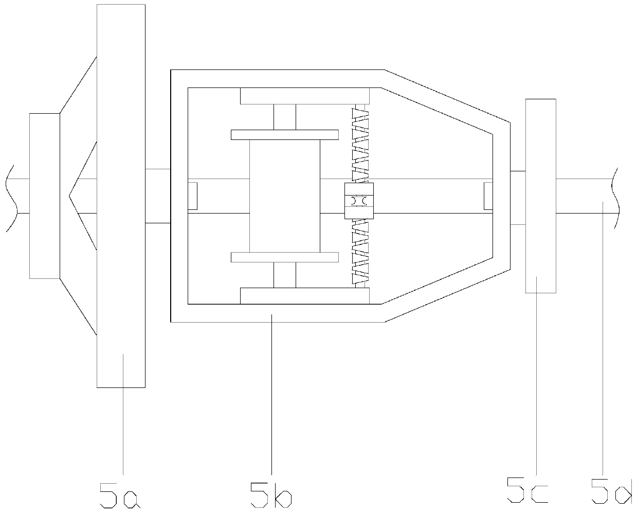
[0030] see Figure 1-Figure 2 , the present invention provides a cable forming machine using centrifugal tension adjustment, its structure includes a control panel 1, a belt drive shaft 2, a drive gear box 3, a cable traction reel 4, a cable cradle frame 5, and the drive gear box 3 is vertically Placed on the floor of the workshop, the control panel 1 is nested on the top right side of the drive gearbox 3, the belt drive shaft 2 is connected through the front of the drive gearbox 3 from top to bottom, and the cable cradle 5. The left side is interlocked with the drive gear box 3. The cable traction plate 4 is a cylindrical structure and the middle of the front is welded together with the right end of the cable cradle frame 5. The cable cradle frame 5 is composed of the first fixed plate 5a, the cradle frame The main body 5b, the second fixed disk 5c, and the driving shaft 5d are composed. The left end of the driving shaft 5d is interlocked with the driving gear box 3. The midd...


PUM


Abstract

The invention discloses a cable-forming machine by utilizing centrifugal adjustment tension. The structure of the cable-forming machine comprises a control panel, a belt drive shaft, a drive gear box,a cable traction disk and a cable cradle frame. Through the combination of a speed regulator and a pre-twist structure, the residual lengths of the cable are different, the cable disks can be outputat different rotation speeds in the cable output twisting process, so that the output lengths of the two cable disks can be ensured to be consistent, the tensions of cable output is unchanged, and thecondition is avoided the cable heights output by the two cable disks are different to cause the hunch-up of the cables in the twisting process and generation of the snake shapes of the cables; and moreover, the pre-twist operation is performed in the cable output process to reduce the condition that the twisting angles are different due to friction in the cable twisting process to generate hunch-up and improve the cable processing quality.

Description

technical field [0001] The invention relates to cable processing equipment, in particular to a cable forming machine using centrifugal tension adjustment. Background technique [0002] With the rapid development of China's electric power construction, the wire and cable industry has developed rapidly, and its demand continues to grow. Cable production is to draw different cables to the twisted cage and then twist them. After twisting, they wrap the outer surface. Different The cable is not well considered in the process of being drawn to the twisted cage, and has the following disadvantages: 1. During the cable processing process, cables of different types are usually placed on the cradle for transportation. In order to ensure the same tension between the cables, gears are usually used to The meshing drives each cable reel to rotate at the same speed and output the cable, but at the same speed, the remaining length of the cable in different cable reels is different, and the ...

Claims


Application Information

Patent Timeline
Patent Type & Authority Applications(China)
IPC IPC(8): H01B13/02
CPCH01B13/02H01B13/0207
Inventor 吴凤明
Owner 诸暨市友利针纺织有限公司
Why Eureka
Try Eureka