Remote monitoring method and monitoring terminal for engineering machinery

A technology for remote monitoring of construction machinery, applied in machine-to-machine/machine-type communication services, services based on location information, short-distance communication services, etc. Theft, monitoring information cannot be effectively transmitted and other problems, to achieve good anti-theft effect, avoid monitoring blind spots, and reduce the effect of operation difficulty

Inactive Publication Date: 2019-10-29
张荣清
View PDF0 Cites 0 Cited by
  • Summary
  • Abstract
  • Description
  • Claims
  • Application Information

AI Technical Summary

Problems solved by technology

[0002] In the existing remote monitoring technology of construction machinery, taking positioning monitoring as an example, the commonly used monitoring methods are as follows: set up a positioning terminal based on GPS / BD on the construction machinery, and combine the mobile communication network to transmit the data collected by the positioning terminal. location information, so as to meet the demand for position monitoring of construction machinery; however, if the monitored construction machinery enters some remote areas that are not covered by the communication network, the monitoring information cannot be effectively transmitted, and the mechanical equipment will lose connection. Based on this, it can be seen that the existing remote monitoring technology for construction machinery is still relatively flawed;
[0003] In addition, most of the positioning terminals proposed above are directly installed on construction machinery, resulting in a greater risk of the positioning terminal itself being damaged or stolen, which will also affect the monitoring effect of the corresponding construction machinery;

Method used


Image

  • Remote monitoring method and monitoring terminal for engineering machinery
  • Remote monitoring method and monitoring terminal for engineering machinery
  • Remote monitoring method and monitoring terminal for engineering machinery

Examples


Embodiment Construction

[0032] The following will clearly and completely describe the technical solutions in the embodiments of the present invention with reference to the accompanying drawings in the embodiments of the present invention. Obviously, the described embodiments are only some, not all, embodiments of the present invention. Based on the embodiments of the present invention, all other embodiments obtained by persons of ordinary skill in the art without making creative efforts belong to the protection scope of the present invention.

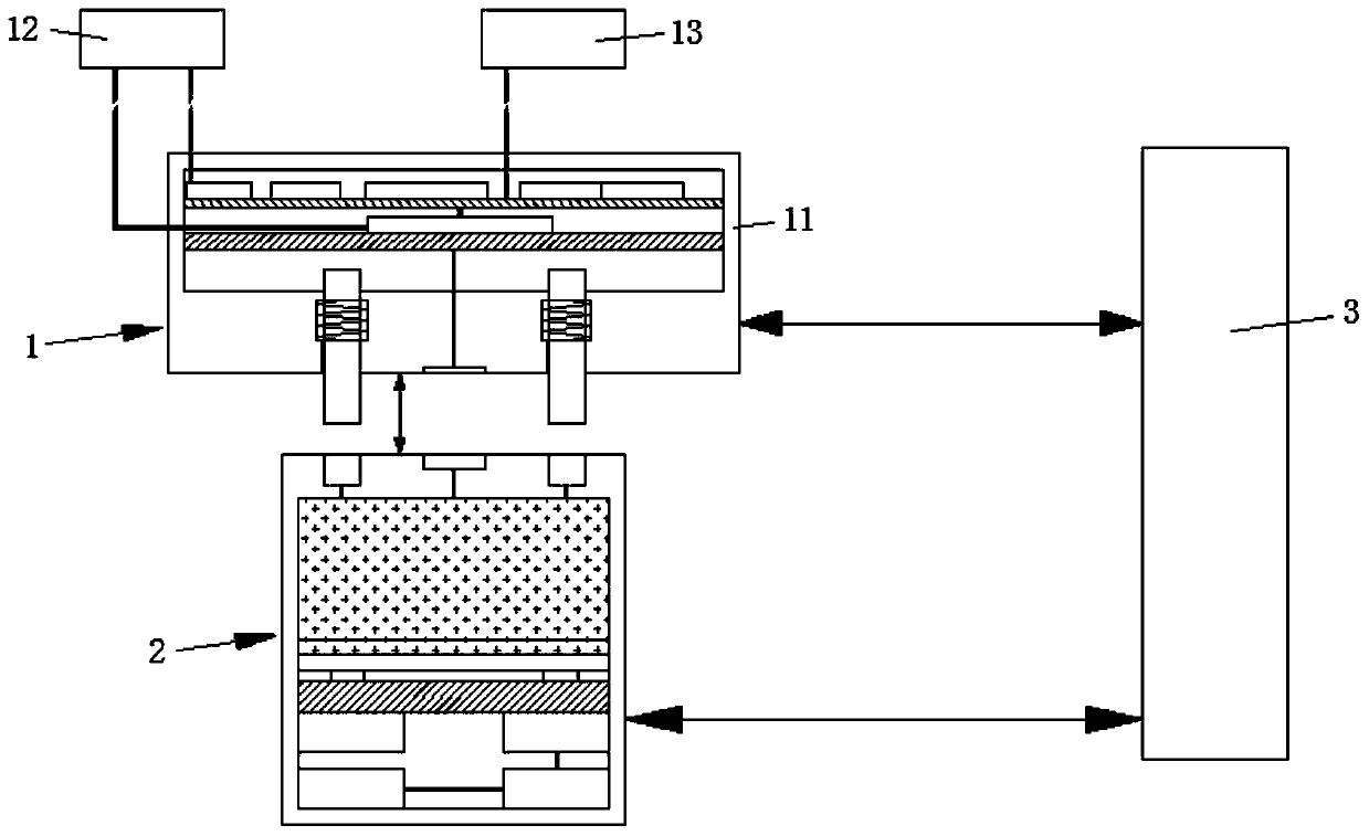
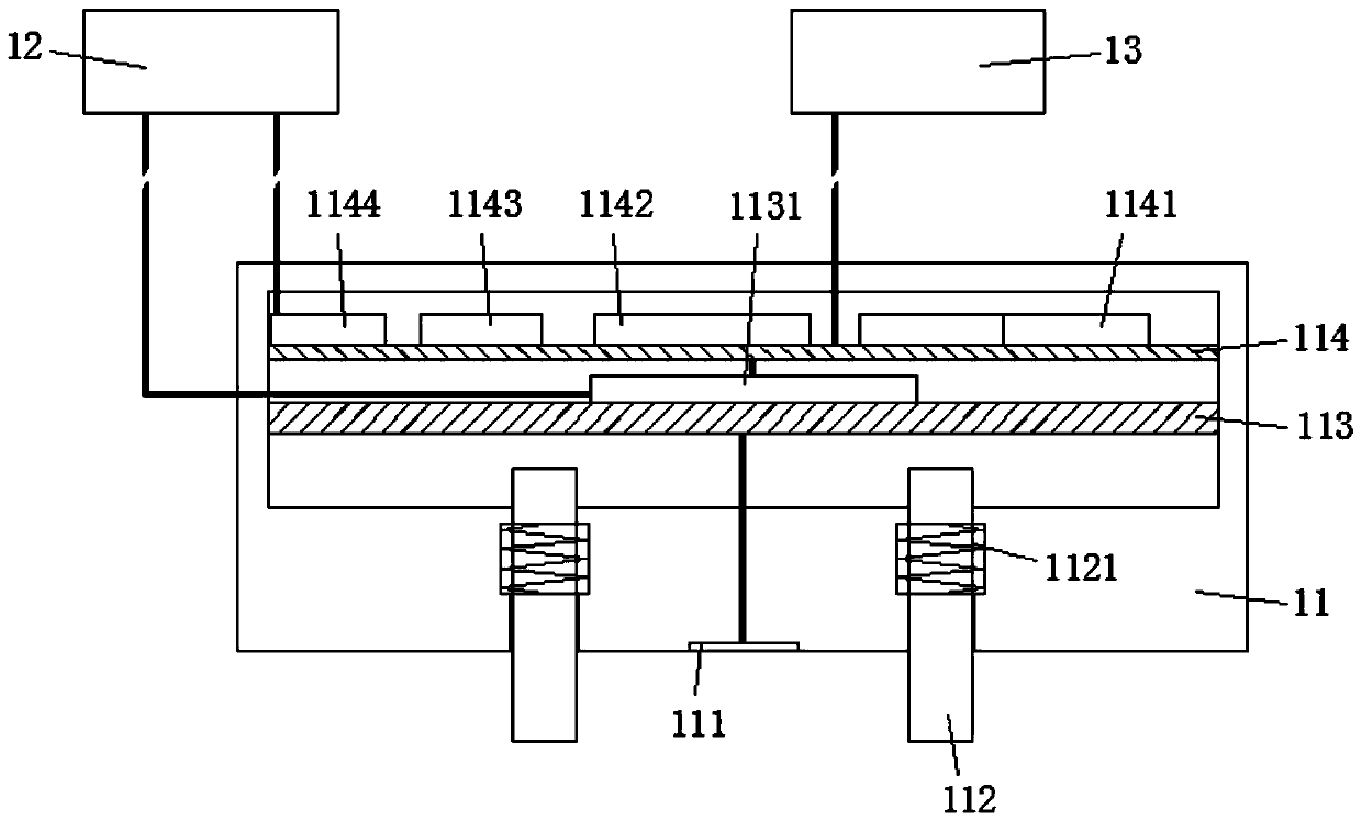
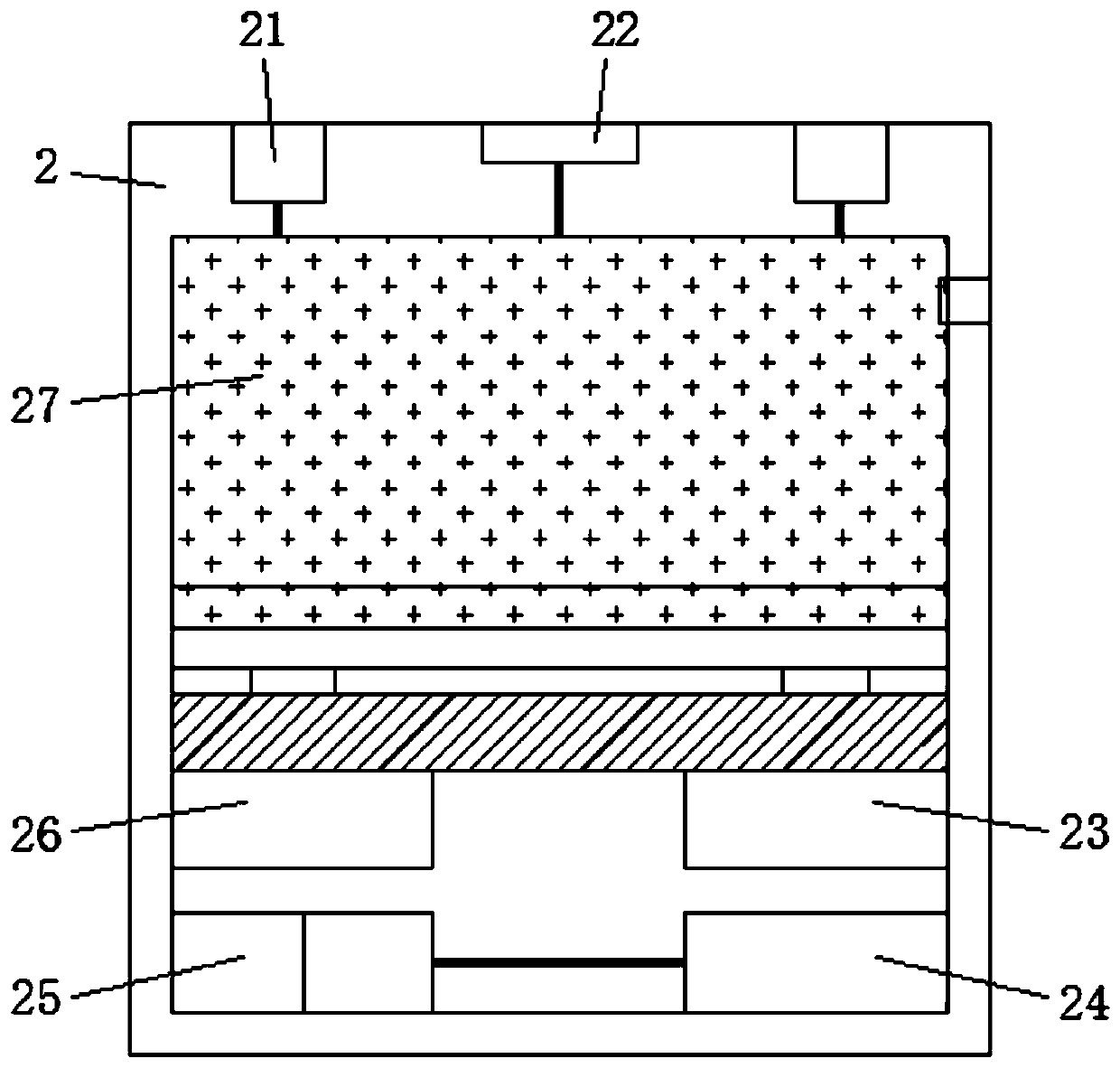
[0033] 1. Please refer to Figure 1-Figure 4 As shown, the present invention provides a remote monitoring terminal for construction machinery, including a built-in terminal 1 and an external terminal 2, wherein the built-in terminal 1 is embedded and installed on each construction machine, and the external terminal 2 and the built-in terminal 1 use a One-to-one, one-to-many or many-to-one pairing;

[0034] The built-in terminal 1 includes a device body 11, a ...


PUM


Abstract

The invention belongs to the technical field of engineering machinery remote monitoring, and discloses an engineering machinery remote monitoring method and a monitoring terminal. The monitoring terminal comprises a built-in terminal and an external terminal, the built-in terminal comprises a device body, a relay and a solenoid valve, and a scanning probe and a conductive column are embedded in the outer wall of one side of the device body; a conductive groove and an electronic tag are embedded in the outer wall of one side of the external terminal, and the conductive groove and the electronictag are respectively matched with the conductive column and the scanning probe for use. The monitoring terminal is divided into the built-in terminal and the external terminal, and the unlocking andstarting of the engineering machinery can be effectively completed only under the condition that the two parts of structures are matched for use, so that the anti-theft effect of the engineering machinery during starting and use is realized; in addition, the two sub-structures need to be matched with an electronic tag for scanning verification during matching, so that the starting and using safetyof the engineering machinery is further improved.

Description

technical field [0001] The invention belongs to the technical field of remote monitoring of engineering machinery, and in particular relates to a remote monitoring method of engineering machinery and a monitoring terminal. Background technique [0002] In the existing remote monitoring technology of construction machinery, taking positioning monitoring as an example, the commonly used monitoring methods are as follows: set up a positioning terminal based on GPS / BD on the construction machinery, and combine the mobile communication network to transmit the data collected by the positioning terminal. location information, so as to meet the demand for position monitoring of construction machinery; however, if the monitored construction machinery enters some remote areas that are not covered by the communication network, the monitoring information cannot be effectively transmitted, and the mechanical equipment will lose connection. Based on this, it can be seen that the existing ...

Claims


Application Information

Patent Timeline
Patent Type & Authority Applications(China)
IPC IPC(8): H04W4/70H04W4/80H04W4/02
CPCH04W4/025H04W4/70H04W4/80
Inventor 张荣清
Owner 张荣清
Why Eureka
Try Eureka