Anti-rotation vacuum sucker device

A vacuum suction cup and anti-rotation technology, which is applied in the direction of transportation and packaging, manipulators, chucks, etc., can solve problems such as the self-rotation of the vacuum suction cup, affecting the normal operation of the vacuum suction cup, and the failure of the suction operation of the vacuum suction cup.

Pending Publication Date: 2019-11-01
SUZHOU KANGHONG INTELLIGENT EQUIP CO LTD
View PDF0 Cites 0 Cited by
  • Summary
  • Abstract
  • Description
  • Claims
  • Application Information

AI Technical Summary

Problems solved by technology

[0003] In the current vacuum suction cup structure, since the general suction cup is connected to the substrate through a connecting pipe for vacuuming, and the general connecting pipe is screwed on the substrate, it is easy to loosen or tighten the suction cup. Cause the self-rotation phenomenon of the vacuum suction cup, which can easily cause the failure of the normal suction operation of the vacuum suction cup and affect the normal operation of the vacuum suction cup

Method used


Image

  • Anti-rotation vacuum sucker device
  • Anti-rotation vacuum sucker device
  • Anti-rotation vacuum sucker device

Examples


Embodiment 1

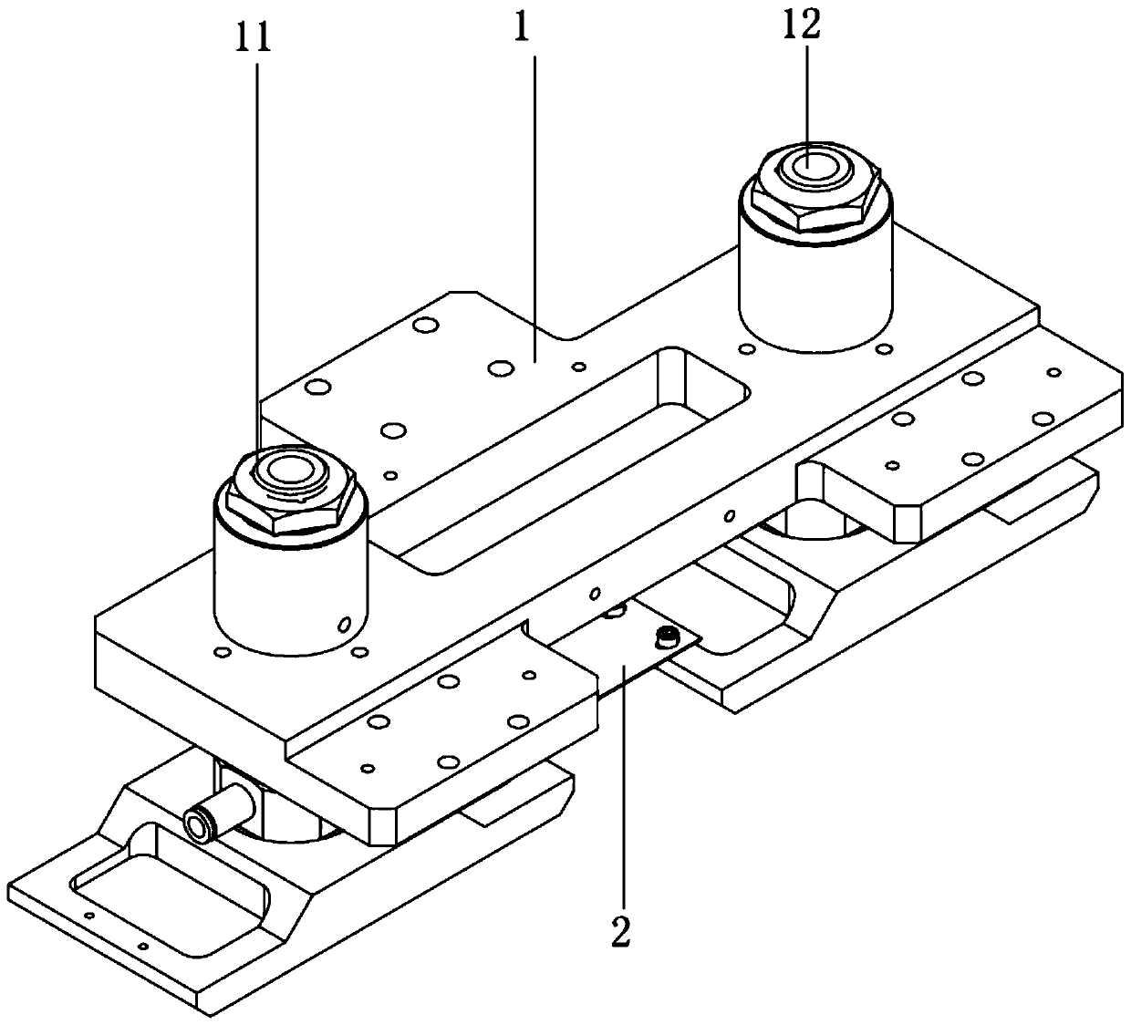
[0027] see Figure 1 to Figure 3 , the figure shows an anti-rotation vacuum chuck device provided by an embodiment of the present invention, including:

[0028] Install substrate 1;

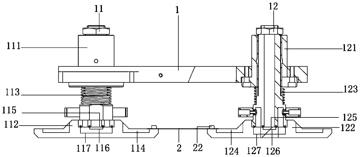
[0029] The first sucker component 11 includes a first connecting rod 111 and a first sucking cup 112, the first sucking cup 112 is fixedly connected to the bottom of the first connecting rod 111, the first connecting rod 111 is passed through the installation substrate 1, and the first A first spring 113 is sleeved on the connecting rod 111, and the first spring 113 is located between the mounting substrate 1 and the first suction cup 112;

[0030] The second sucker component 12 includes a second connecting rod 121 and a second sucking cup 122, the second sucking cup 122 is fixedly connected to the bottom of the second connecting rod 121, the second connecting rod 121 is passed through the installation substrate 1, and the second A second spring 123 is sleeved on the connecting rod 121, and the...

Embodiment 2

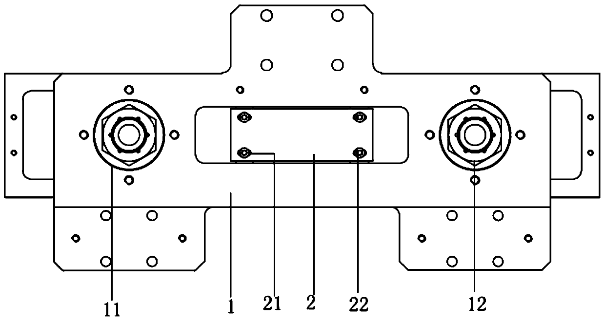
[0040] see Figure 1 to Figure 3 , the figure shows an anti-rotation vacuum chuck device provided by Embodiment 2 of the present invention. On the basis of the above embodiment, this embodiment further makes the following technical solution as an improvement: the connecting shrapnel 2 is rectangular shrapnel.

[0041] Since both the first suction cup and the second suction cup are square suction cups, the two ends of the rectangular shrapnel better match the edges of the suction cups, thereby achieving a better limiting effect.

Embodiment 3

[0043] see Figure 1 to Figure 3 , the figure shows a anti-rotation vacuum chuck device provided by the third embodiment of the present invention. On the basis of the above embodiment, this embodiment further makes the following technical solutions as improvements: the first connecting rod 111 The bottom of the first suction cup 112 is snapped into the preset first slot 115 on the top of the first suction cup 112, and a concentrically arranged first inner seal is installed between the bottom surface of the first connecting rod 111 and the bottom of the first slot 115. Ring 116 and the first outer sealing ring 117. The bottom of the second connecting rod 121 is snapped into the preset second slot 125 on the top of the second suction cup 122, and a concentric arrangement is installed between the bottom surface of the second connecting rod 121 and the bottom of the second slot 125. The second inner sealing ring 126 and the second outer sealing ring 127.

[0044] There are two l...


PUM


Abstract

The invention provides an anti-rotation vacuum sucker device. The anti-rotation vacuum sucker device comprises a mounting substrate, a first sucker component, a second sucker component and a connecting elastic sheet; the first sucker component comprises a first connecting rod and a first sucker, the first sucker is fixedly connected to the bottom of the first connecting rod, the first connecting rod is arranged in the mounting substrate in a penetrating mode, a first spring sleeves the first connecting rod, and the first spring is located between the mounting substrate and the first sucker; the second sucker component comprises a second connecting rod and a second sucker, the second sucker is fixedly connected to the bottom of the second connecting rod, the second connecting rod is arranged in the mounting substrate in a penetrating mode, a second spring sleeves the second connecting rod, and the second spring is located between the mounting substrate and the second sucker; and the twoopposite ends of the connecting elastic sheet are fixedly connected to the first sucker and the second sucker correspondingly. According to the anti-rotation vacuum sucker device, the self-rotation phenomenon caused by loosening or suction of the suckers can be effectively prevented, and the stability of vacuum sucker suction operation is guaranteed.

Description

technical field [0001] The invention relates to a vacuum chuck, in particular to an anti-rotation vacuum chuck device. Background technique [0002] Vacuum chuck is a technology that maintains the attachment of two objects without separation through the degree of vacuum. There are industrial applications and civil applications. In the industry, the "holding" and "putting" in the process of handling and migration are realized by changing the vacuum degree of the suction cup, and the automation and mechanization are realized together. At present, vacuum suction cups are widely used in many fields. For example, vacuum suction cups are a relatively key component in products such as window cleaning robots that are currently more popular. [0003] In the current vacuum suction cup structure, since the general suction cup is connected to the substrate through a connecting pipe for vacuuming, and the general connecting pipe is screwed on the substrate, it is easy to loosen or tight...

Claims


Application Information

Patent Timeline
IPC IPC(8): B25J15/06B65G47/91
CPCB25J15/0683B65G47/91
Inventor 赵国满邓玉平柴新玉
Owner SUZHOU KANGHONG INTELLIGENT EQUIP CO LTD
Why Eureka
Try Eureka