
Electronic rotor mechanism

A technology of electronic rotor and rotating shaft, which is applied in the direction of magnetic circuit rotating parts, magnetic circuit shape/style/structure, etc., can solve the problems of iron core material waste, heavy weight, and increase the overall weight of electronic motors, etc., and achieve reduction Small weight, the effect of reducing the overall weight

Pending Publication Date: 2019-11-01
张家港市众利机电制造有限公司
View PDF0 Cites 0 Cited by
  • Summary
  • Abstract
  • Description
  • Claims
  • Application Information

AI Technical Summary

Problems solved by technology

[0003] At present, most of the iron cores on the existing electronic rotors are a whole piece. This form of iron core is wasteful in the use of materials, and at the same time, it is heavy, which will increase the overall weight of the electronic motor. In addition, this form of electronic rotor The length of the iron core generally can only be used for the same type of electronic motor, and the applicability is not strong

Method used


Image

  • Electronic rotor mechanism
  • Electronic rotor mechanism
  • Electronic rotor mechanism

Examples


Embodiment

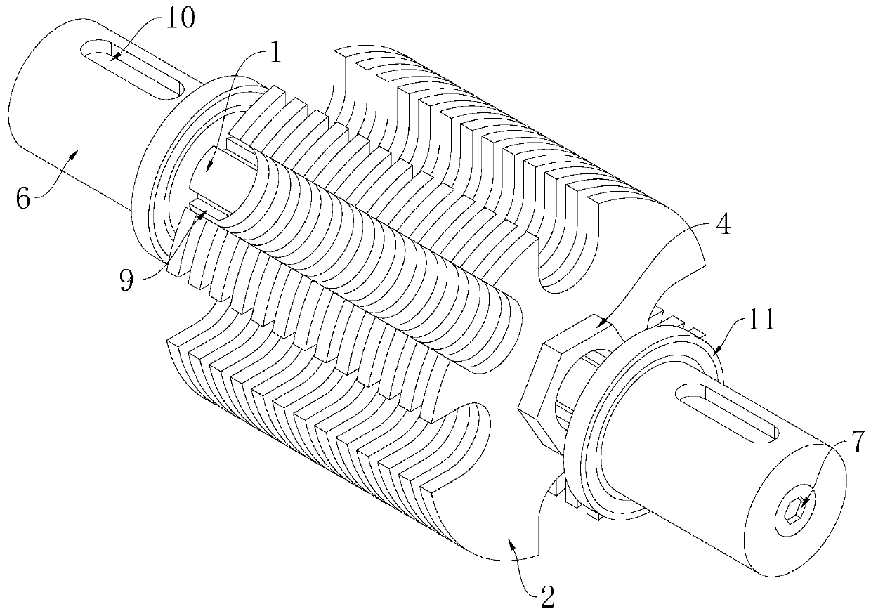
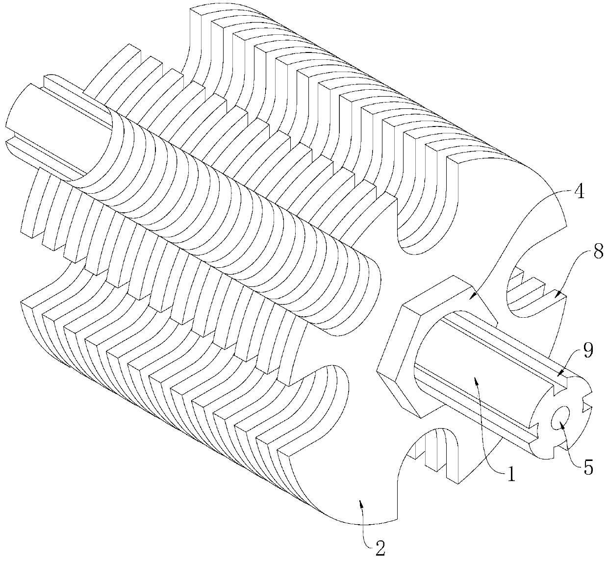
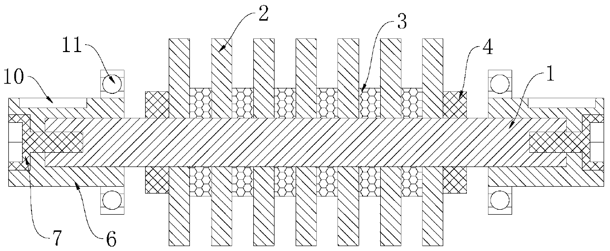
[0022] Example: such as figure 1 , figure 2 and image 3 As shown, an electronic rotor mechanism of the present invention includes a rotating shaft 1 and several fixed steel sheets 2, and several fixed steel sheets 2 are all slidably sleeved on the outer surface of the rotating shaft 1, and two adjacent fixed steel sheets 2 The sliding sleeve on the rotating shaft 1 between them is provided with spacer steel sheets 3, and the two ends of the outer surface of the rotating shaft 1 are all threaded with fastening nuts 4, and the opposite sides of the two fastening nuts 4 are respectively connected to the rotating shaft 1. The fixed steel sheets 2 at both ends are tightly fitted, the middle part of both ends of the rotating shaft 1 is provided with a threaded hole 5, and the two ends of the rotating shaft 1 are movably sleeved with a rotating shaft cap 6, and the middle parts of the opposite sides of the two rotating shaft caps 6 are arranged. Jacks are provided, fastening bolt...


PUM


Abstract

The invention discloses an electronic rotor mechanism. The electronic rotor mechanism comprises a rotating shaft and a plurality of fixed steel sheets, and the plurality of fixed steel sheets slidablysleeve on the outer surface of the rotating shaft, and the rotating shaft between two adjacent fixed steel sheets is slidingly sleeved with a space steel sheet, the two ends of the outer surface of the rotating shaft is sleeved with fastening nuts in a threaded mode, the opposite sides of the two fastening nuts are respectively tightly applied to the fixed steel sheets located at the two ends ofthe rotating shaft, the middle portions of the two ends of the rotating shaft are provided with threaded holes, the two ends of the rotating shaft are movably sleeved with rotating shaft caps, the middle portions of the opposite sides of the two rotating shaft caps are provided with jacks respectively, and the fastening nuts are inserted into the jacks. The fixed steel sheets and the space steel sheets are mutually stacked and are fixed at the surface of the rotating shaft to consume little materials and effectively reduce the whole weight of the electronic rotor so as to effectively reduce the whole weight of the electronic rotor.

Description

technical field [0001] The invention relates to a rotor mechanism, in particular to an electronic rotor mechanism. Background technique [0002] The electronic rotor is the rotatable part of the electronic motor. An armature winding is installed on it. After being energized, an induced electromotive force is generated, which acts as a rotating magnetic field and generates an electromagnetic torque for energy conversion. [0003] At present, most of the iron cores on the existing electronic rotors are a whole piece. This type of iron core consumes more materials and is heavier, which will increase the overall weight of the electronic motor. In addition, this type of electronic rotor Generally, the iron core length can only be used for the same type of electronic motor, and the applicability is not strong. Therefore, we improve this and propose an electronic rotor mechanism. Contents of the invention [0004] In order to solve the problems of the technologies described abo...

Claims


Application Information

Patent Timeline
IPC IPC(8): H02K1/22
CPCH02K1/22
Inventor 周任义
Owner 张家港市众利机电制造有限公司
Learn More