Co-location interference suppression method based on optical processing

A technology of co-site interference and optical processing

Inactive Publication Date: 2019-11-01
NO 34 RES INST OF CHINA ELECTRONICS TECH GRP
View PDF7 Cites 0 Cited by
  • Summary
  • Abstract
  • Description
  • Claims
  • Application Information

AI Technical Summary

Problems solved by technology

[0004] The problem to be solved by the present invention is the co-site inte

Method used


Image

  • Co-location interference suppression method based on optical processing
  • Co-location interference suppression method based on optical processing
  • Co-location interference suppression method based on optical processing

Examples


Embodiment 1

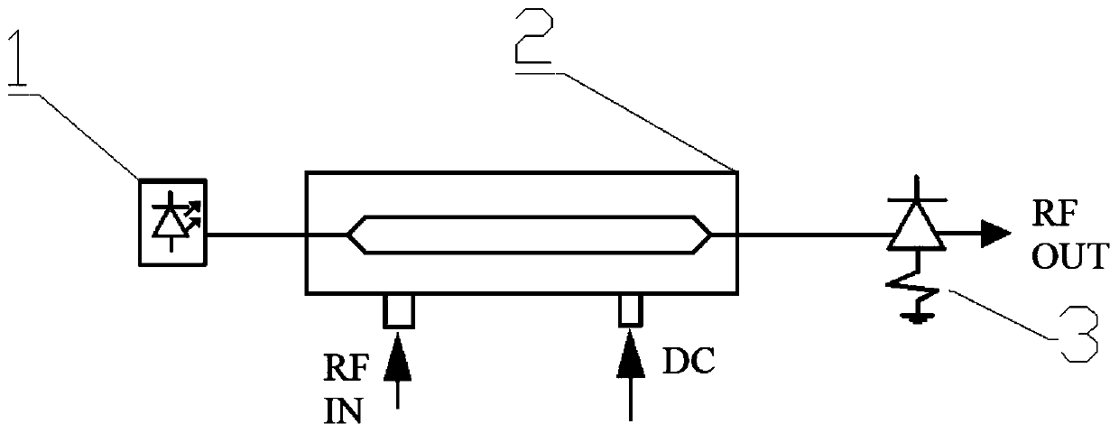
[0025] This embodiment provides a method for suppressing co-site interference based on optical processing. The description of the method is as follows Figure 4 As shown, the co-site interference suppression method is as follows:

[0026] Step 1, define the link RF input signal as V(t)=V D +V S sin(ω s t)+V N sin(ω N t), where V D is a DC signal, V S sin(ω s t) is useful signal, V N sin(ω N t) is an interference signal;

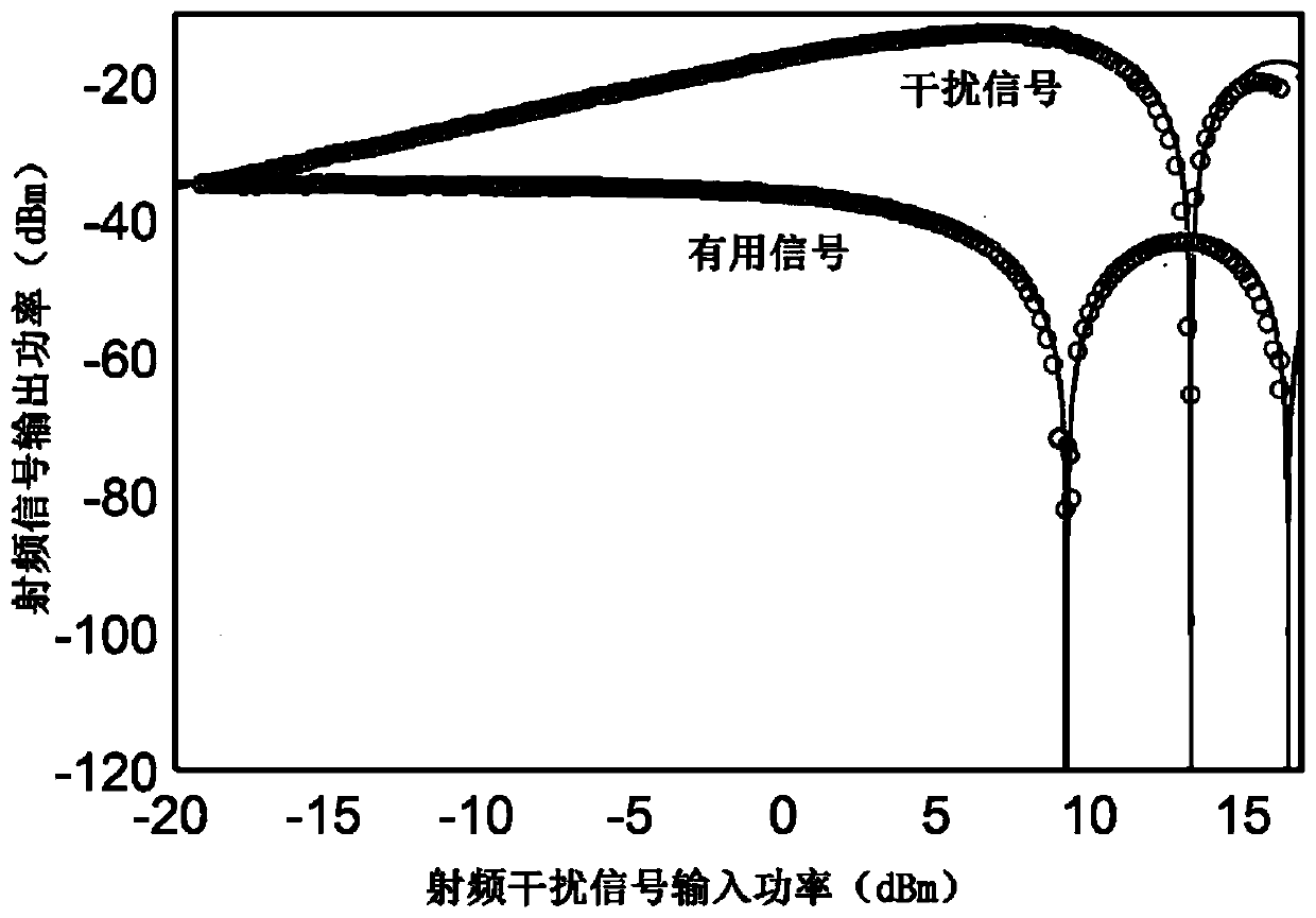
[0027] Step 2, define the output power of the interference signal

[0028] The rate is: Among them, H pd is the frequency response of the photodetector circuit, J is the Bessel function of the first kind, and I dc is the photocurrent of MZM;

[0029] Step three, calculate root of From this, the required input interference signal power is calculated when the output interference signal is suppressed

[0030] Among them, V π is the half-wave voltage of the Mach-Zehnder modulator;

[0031] Step 4, control the power of the input signal ...


PUM


Abstract

The invention provides an co-location interference suppression method based on optical processing. According to the method, the problem of radio frequency co-location interference is processed on a photonic link, and the suppression of the co-location interference is realized by utilizing the special transmission characteristics of the MZM-based photonic link. The photon link signal output power based on the MZM is firstly increased and then decreased along with the increase of the radio frequency signal input power, and finally the phenomenon that zero points and peak values are periodicallyalternated occurs. By controlling the input power of the interference signal, the output power of the interference signal is enabled to be at a zero point, same-address interference suppression is realized, and the suppression ratio reaches 78dB. Meanwhile, corresponding suppression conditions can be obtained through calculation according to the input of radio frequency signals with different frequencies, so that the same-address interference suppression in a broadband range can be realized.

Description

technical field [0001] The invention relates to the field of microwave photons, in particular to a co-site interference suppression method based on optical processing. Background technique [0002] In the field of wireless communication, the problem of co-site interference has always been a hot spot that researchers pay attention to. Co-site interference means that when the transmitting antenna is close to the receiver, the transmitted signal enters the receiver through the receiving antenna and interferes with the useful signal, which poses a great challenge to the dynamic range and sensitivity of the receiver. People have invested a lot of resources to solve the problem of co-site interference, and have achieved some results in both theory and application. Initially, the elimination of co-site interference was started from the perspective of analog circuits or digital circuits, but this traditional method of electrical signal processing has problems such as limited bandwi...

Claims


Application Information

Patent Timeline
IPC IPC(8): H04B10/54H04B10/564
CPCH04B10/54H04B10/564
Inventor 杨万里朱宏韬宋文忠尹怡辉陈协助
Owner NO 34 RES INST OF CHINA ELECTRONICS TECH GRP
Why Eureka
Try Eureka