Heavy take-up and pay-off machine

A wire take-up and pay-off machine, heavy-duty technology, applied in the field of heavy-duty take-up and pay-off machines, can solve the problems that the wire retaining board cannot be adjusted, and there is no wire retaining board.

Active Publication Date: 2019-11-05
JIANGSU HONTA MACHINERY
View PDF9 Cites 2 Cited by
  • Summary
  • Abstract
  • Description
  • Claims
  • Application Information

AI Technical Summary

Problems solved by technology

The fast, safe and reliable function of retracting and unwinding the cables must be realized during on-site operations; however, the existing winding rollers have no wire retaining plates at both ends after the cables are wound, and the wire r...

Method used


Image

  • Heavy take-up and pay-off machine
  • Heavy take-up and pay-off machine
  • Heavy take-up and pay-off machine

Examples


Embodiment Construction

[0018] The content of the present invention will be further described in detail below in conjunction with the accompanying drawings.

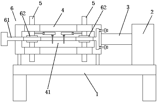
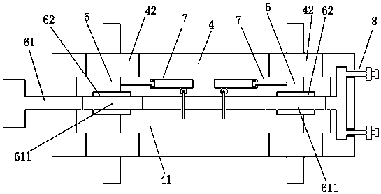
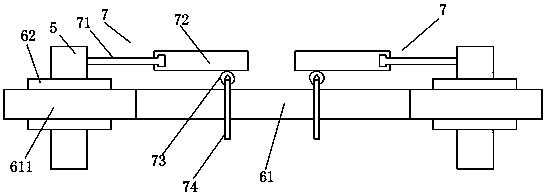
[0019] Such as Figures 1 to 5 As shown, a heavy-duty take-up and pay-off machine includes a frame 1, a drive mechanism 2, a rotating shaft 3, and a winding roller 4; the drive mechanism 2 is installed on the upper end side of the frame 1; the drive mechanism 2 Connected to one end of the winding roller 4 through the rotating shaft 3; it also includes two wire retaining plates 5 and a drive assembly 6; the inside of the winding roller 4 is provided with a drive cavity 41; the two retaining plates 5 are along the The axial direction of the winding roller 4 is slid and clamped on both ends of the winding roller 4 respectively; the outer sides of the wire retaining plate 5 are located on the outer side of the winding roller 4; the driving assembly 6 includes two driving threads A cylinder 62 and a drive rod 61; a drive thread cylinder 62 is fixed...


PUM


Abstract

The invention discloses a heavy take-up and pay-off machine. The heavy take-up and pay-off machine comprises a machine frame, a driving mechanism, a rotating shaft and a wire winding roller; the driving mechanism is arranged on one side of the upper end of the machine frame; the driving mechanism is connected to one end of the wire winding roller through the rotating shaft; the take-up and pay-offmachine further comprises two wire baffle plates and a driving assembly; a driving cavity is formed in the wire winding roller; the two wire baffle plates are glidingly clamped at the two ends of thewire winding roller in the axial direction of the wire winding roller; the outer sides of the peripheries of the wire baffle plates are located on the outer side of the wire winding roller; and the driving assembly comprises two driving threaded barrels and a driving rod. According to the heavy take-up and pay-off machine, the positions of the wire baffle plates can be adjusted, the adjustment isvery convenient, and the structure is stable.

Description

technical field [0001] The invention relates to a heavy-duty take-up and pay-off machine. Background technique [0002] At present, the output cables of large-scale emergency mobile rescue vehicles, such as emergency power supply vehicles and emergency flood fighting vehicles, are multi-strand heavy-duty cables. The fast, safe and reliable function of retracting and unwinding the cables must be realized during on-site operations; however, the existing winding rollers have no wire retaining plates at both ends after the cables are wound, and the wire retaining plates cannot The winding length of the cable is adjusted. The position of the wire blocking plate on the winding roller is used to limit the position of the cable, and it is necessary to ensure the stability of the structure and the convenience of adjustment. Contents of the invention [0003] Aiming at the shortcomings of the above-mentioned prior art, the problem to be solved by the present invention is: to provid...

Claims


Application Information

Patent Timeline
IPC IPC(8): B65H75/38B65H75/44B65H75/24
CPCB65H75/241B65H75/38B65H75/4481
Inventor 谭礼春
Owner JIANGSU HONTA MACHINERY
Why Eureka
Try Eureka