Portable foundation pit monitoring device and use method

A technology for monitoring devices and foundation pits, which can be used in on-site foundation soil surveys, infrastructure engineering, construction, etc., can solve problems such as inconvenient installation, high cost, and low test efficiency, achieve rapid replacement and repair, improve measurement accuracy, The effect of reducing the difficulty of transportation and installation

Inactive Publication Date: 2019-11-05
杭州瑞纽宝科技有限公司
View PDF6 Cites 2 Cited by
  • Summary
  • Abstract
  • Description
  • Claims
  • Application Information

AI Technical Summary

Problems solved by technology

[0004] The present invention overcomes the above-mentioned difficulties in the current technology. The present invention proposes a portable foundation pit monitoring device and its use method, which solves the problems of high cost, inconvenient installation and low testing efficiency of the existing foundation pit monitoring equipment.

Method used


Image

  • Portable foundation pit monitoring device and use method
  • Portable foundation pit monitoring device and use method
  • Portable foundation pit monitoring device and use method

Examples


Embodiment 1

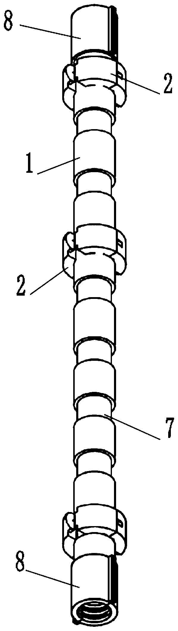
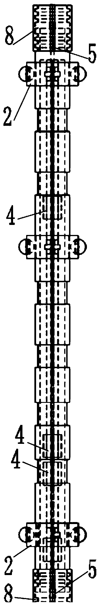
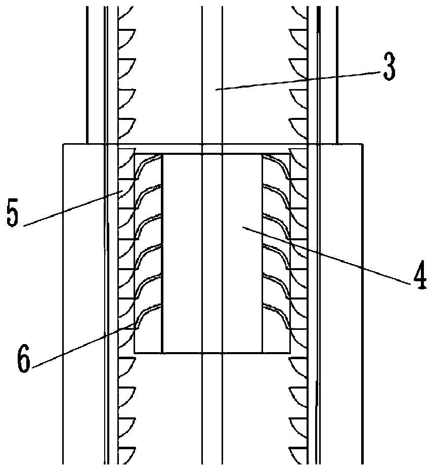
[0041] Such as Figure 1-8 As shown, the present invention provides a portable foundation pit monitoring device, which includes a protective tube formed by connecting multiple protective sub-pipes 1 through a connector 8, and at least two centralizers 2 are fixed on the outer wall of each protective sub-pipe 1 to protect The inner wall of the sub-tube 1 has a guide rail 3, at least one of the protective sub-tubes 1 is provided with a monitoring module 4, and the monitoring module 4 is slidably socketed on the guide rail 3, and a monitoring module 4 is provided between the inner wall of the protective sub-tube 1 and the monitoring module 4. A limit structure that can only move upward along its long axis. The number and position of the monitoring modules 4 in the protection tube can be customized by the user. The monitoring modules 4 transmit the monitoring data through the data transmitter.

[0042] Such as image 3 As shown, in one embodiment of the present application, the l...

Embodiment 2

[0065] Such as Figure 8 and Figure 9 As shown, a portable foundation pit monitoring device in this embodiment includes a protective tube formed by connecting multiple protective sub-pipes 1 through a connector 8, and at least two centralizers 2 are fixed on the outer wall of each protective sub-pipe 1 , At least one of the protective sub-tubes 1 is provided with a monitoring module 4, and the monitoring module 4 is fixed on the inner wall of the protective sub-tube 1. The number and position of the monitoring modules 4 in the protective tube and the number and position of the centralizer 2 are defined by the user , the monitoring module 4 transmits the monitoring data through the data transmitter. The centralizer 2 is fixed on the outer wall of the protective sub-pipe 1 with screws. The monitoring module 4 is fixed on the inner wall of the protective sub-tube 1 with screws. The protective sub-pipe 1 is formed by fixedly connecting two semicircular pipes 9 .


PUM


Abstract

The invention discloses a portable foundation pit monitoring device. The device comprises a protection tube formed by connecting a plurality of protection sub-tubes by connectors, wherein at least twocentralizers are fixed on the outer wall of each protection sub-tube, guide rails are arranged on the inner walls of the protection sub-tubes, and a monitoring module is arranged in at least one of the protection sub-tubes and sleeves the guide rails in a sliding manner; limit structures are arranged between the inner walls of the protection sub-tubes and the corresponding monitoring modules; thenumber and the position of the monitoring modules arranged in the protection tube and the number and the position of the centralizers are defined by users; the monitoring modules transmit monitoringdata through a data transmitter. The monitoring modules are designed in a modular manner, the users can increase or decrease the number of the monitoring modules in the designated area, the number ofthe monitoring modules can be properly increased or decreased according to monitoring requirements, and thus, the cost is reduced, and measurement accuracy is improved.

Description

technical field [0001] The invention relates to the technical field of engineering monitoring, in particular to a portable foundation pit monitoring device and a use method. Background technique [0002] The inclinometer is often used in engineering safety monitoring. The sliding inclinometer has a steel monitoring module, and the inclinometer is manually drawn. When the inclinometer head is at a certain depth, manual reading is performed. This test method works efficiently. Low, labor-intensive. Due to the high cost of the traditional inclinometer and the low modularity of each component, it is not convenient for monitoring personnel to install and maintain it at the monitoring point. [0003] Therefore, it is very meaningful to propose a foundation pit monitoring device that is easy to install and maintain, can conveniently adjust the monitoring module, and is cheap. Contents of the invention [0004] The present invention overcomes the above-mentioned difficulties in ...

Claims


Application Information

Patent Timeline
Patent Type & Authority Applications(China)
IPC IPC(8): E02D1/00
CPCE02D1/00
Inventor 崔晓铁周浩
Owner 杭州瑞纽宝科技有限公司
Why Eureka
Try Eureka