
Elevator door guide shoe abrasion testing device and method

A testing device and elevator door technology, applied in the elevator field, can solve the problems of increased development cost, time-consuming and labor-intensive, inability to accurately adjust the pressure value of door guide shoes, etc., and achieve the effect of saving development cost and shortening development cycle.

Pending Publication Date: 2019-11-05
MITSUBISHI ELECTRIC SHANGHAI ELECTRIC ELEVATOR
View PDF0 Cites 1 Cited by
  • Summary
  • Abstract
  • Description
  • Claims
  • Application Information

AI Technical Summary

Problems solved by technology

Although this method can measure the wear amount of the door guide shoe, it cannot accurately adjust the pressure value of the pressure surface of the door guide shoe, and cannot do quantitative analysis, and it is time-consuming and labor-intensive, which greatly increases the development cycle and increases the development cost.

Method used


Image

  • Elevator door guide shoe abrasion testing device and method
  • Elevator door guide shoe abrasion testing device and method
  • Elevator door guide shoe abrasion testing device and method

Examples


Embodiment 1

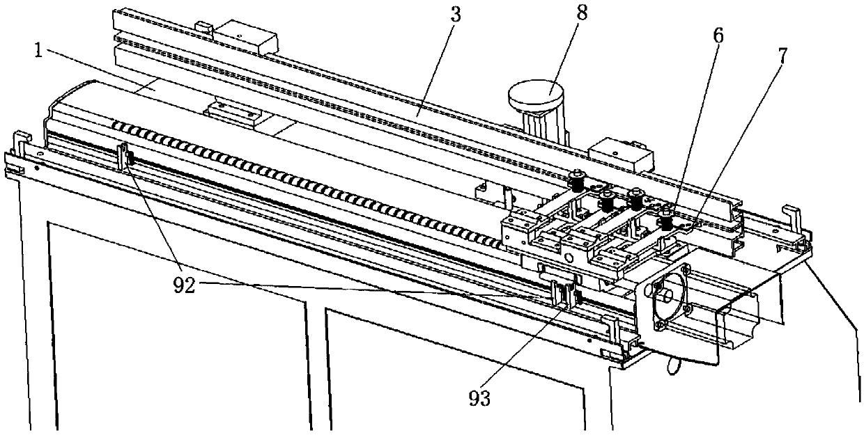
[0057] Such as figure 1 , figure 2 , image 3 , Figure 4 and Figure 5 As shown, the elevator door guide shoe wear test device includes a workbench 1, a linear guide rail 2, an elevator sill 3, a ball screw pair 4, a mounting seat 5, and a pressure adjustment device 6;

[0058] The linear guide rail 2, the ball screw pair 4, and the elevator sill 3 are sequentially fixed on the top of the workbench 1 from back to front;

[0059] The direction of the linear guide rail 2 and the elevator sill 3 are all parallel to the screw axis of the ball screw pair 4;

[0060] The elevator sill 3 can move back and forth;

[0061] The screw of the ball screw pair 4 can rotate along its axis;

[0062] The middle part of the mounting seat 5 is fixed on the nut of the ball screw pair 4;

[0063] The lower part of the rear part of the mounting base 5 abuts against the upper surface of the linear guide rail 2;

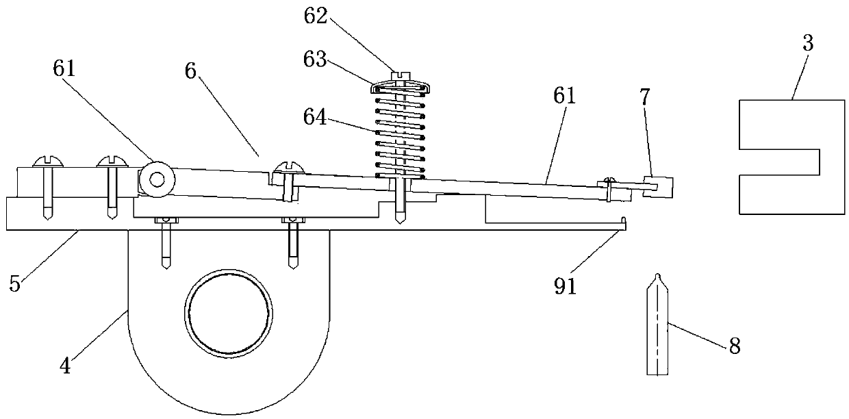
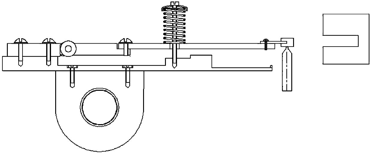
[0064] The pressure adjusting device 6 includes a connecting rod 61, a screw 62...

Embodiment 2

[0074] Based on the first embodiment, the elevator door guide shoe wear test device also includes a force measuring device 8;

[0075] The force measuring device 8 includes a pressure sensor and its driving guide; the driving guide is fixed on the workbench 1;

[0076] The pressure sensor can be extended toward the front end of the connecting rod 61 or retracted toward the workbench 1 under the driving of the driving guide device.

[0077] In the elevator door guide shoe wear test device of the second embodiment, the driving and guiding device of the force measuring device 8 can drive the probe of the pressure sensor to move and withstand the door guide shoe 7 fixed at the front end of the connecting rod when force measurement is required. After the force is completed, the pressure sensor probe is driven back to its original position by the driving guide device, which will not block the backward movement of the elevator sill 3, so that the elevator sill 3 moves backward so tha...

Embodiment 3

[0079] Based on the second embodiment, the elevator door guide shoe wear test device also includes a laser ranging sensor 90;

[0080] The laser ranging sensor 90 is used to detect the thickness of the door guide shoe 7 fixed on the front end of the connecting rod 61 .

[0081] Preferably, the screw hole at the front of the mounting seat 5 is a boss;

[0082] The front end of the mounting seat 5 is located directly below the front end of the connecting rod;

[0083] The laser ranging sensor is arranged at the front end of the mounting base.


PUM


Abstract

The invention discloses an elevator door guide shoe abrasion testing device. The device comprises a workbench, a linear guide rail, an elevator sill, a ball screw pair, an installing base and a pressure adjustment device, wherein the middle of the installing base is fixed to a nut of the ball screw pair; the bottom of the rear portion of the installing base abuts against the upper surface of the linear guide rail; the pressure adjustment device comprises a connecting rod, a screw, a spring cap and a spiral spring; the rear end of the connecting rod is hinged to the rear portion of the installing base; after the screw penetrates through the spring cap, the spiral spring and the connecting rod sequentially, the lower end of the screw is fixed into a screw hole in the front portion of the installing base; the front end of the connecting rod is located behind the elevator sill, and the connecting rod is used for fixing a door guide shoe; and a servo motor is used for driving a lead screw of the ball screw pair to rotate. The invention further discloses an elevator door guide shoe abrasion testing method. Through the testing device and method, back-and-forth sliding of the guide shoe inthe elevator sill can be quickly simulated in a set pressure state, elevator door guide shoe abrasion is quickly tested, the door guide shoe development cycle is shortened, and development cost is saved.

Description

technical field [0001] The invention relates to elevator technology, in particular to an elevator door guide shoe wear test device and a test method. Background technique [0002] Elevator door guide shoes, as the guide parts of the elevator hall door and car door, continuously form sliding friction with the guide surface of the elevator sill when the elevator opens and closes the door, and need to carry long-term friction loads. Its general operating life is 2 to 3 years. It needs to be replaced after 2 to 3 years. However, judging from the actual operating status at the construction site, some door guide shoes have been severely worn within half a year and had to be replaced. [0003] Therefore, how to judge that the door guide shoe designed and manufactured by the elevator company can meet its life requirements is a problem that the elevator company must consider from the development stage of the door guide shoe. Elevator design and manufacturing companies are generally...

Claims


Application Information

Patent Timeline
IPC IPC(8): G01N3/56
CPCG01N3/56G01N2203/0005G01N2203/005G01N2203/0423
Inventor 陈谢刘尊柱傅武军盛锦俊
Owner MITSUBISHI ELECTRIC SHANGHAI ELECTRIC ELEVATOR
Features
  • Generate Ideas
  • Intellectual Property
  • Life Sciences
  • Materials
  • Tech Scout
  • Unparalleled Data Quality
  • Higher Quality Content
  • 60% Fewer Hallucinations
Learn More