Sheath connecting structure of combined cables

A technology of combining cables and connecting structures, applied in electrical components and other directions, can solve problems such as inconvenience in operation, and achieve the effect of avoiding water infiltration and working environment safety.

Inactive Publication Date: 2019-11-05
YANCHENG KEHENGDA MATERIALS CO LTD
0 Cites 0 Cited by

AI-Extracted Technical Summary

Problems solved by technology

The sheaths of adjacent combined cables need to be connected and fixed. Traditionally, the...

Abstract

The invention discloses a sheath connecting structure of combined cables. The sheath connecting structure includes an outer sheath. An inner sheath is inserted into the outer sheath. A first annular slot is arranged in the inner wall of the outer sheath. The inner wall of the first annular slot is rotationally connected with a plurality of butting rods. A compression spring is fixedly connected between each butting rod and the inner wall of the first annular slot. A second annular slot is arranged in the inner wall of the inner sheath. Multiple semicircular blocks are fixed on the inner wall of the second annular slot. A sealing sleeve is fixed on the inner wall of the outer sheath. A third annular slot is arranged in one end, away from the outer sheath, of the sealing sleeve. A flanging turned inward is integrally formed on the inner wall of the third annular slot. By inserting the inner sheath into the outer sheath and clamping the butting rods into the second annular slot, the innersheath can be fixed, the sheaths can be connected, and the joints of cables can be protected. By setting the sealing sleeve, water infiltration is avoided, and the working environment is safer.

Application Domain

Electrical apparatus

Technology Topic

FlangingEngineering +1

Image

  • Sheath connecting structure of combined cables
  • Sheath connecting structure of combined cables
  • Sheath connecting structure of combined cables

Examples

  • Experimental program(1)

Example Embodiment

[0018] The technical solutions in the embodiments of the present invention will be clearly and completely described below in conjunction with the drawings in the embodiments of the present invention.
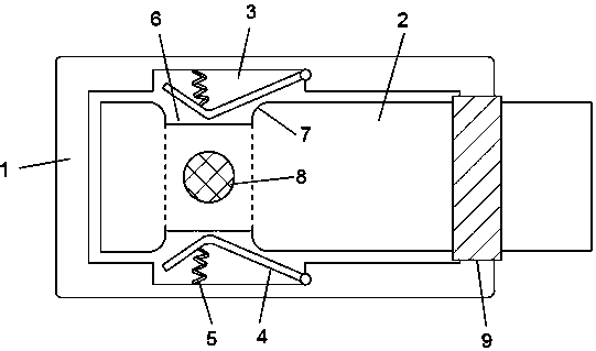
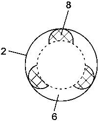
[0019] Reference Figure 1-3 , The sheath connection structure of the combined cable includes a jacket 1, the jacket 1 is inserted with an inner jacket 2, the inner wall of the jacket 1 is provided with an annular groove 3, and the inner wall of the annular groove 3 is rotatably connected with a plurality of levers 4 A compression spring 5 is fixedly connected between each abutment rod 4 and the inner wall of the annular groove one 3. The outer wall of the inner sleeve 2 is provided with an annular groove two 6. It is further explained that the abutment rod 4 is inserted into the annular groove two 6 The internal compression spring 5 is not fully expanded to ensure the elastic force to fix the inner sleeve 2. A number of semicircular blocks 8 are fixed on the inner wall of the annular groove 2 6, the number of the push rod 4 is three, and the number of semicircular blocks 8 is Three. The radius of the semicircular block 8 matches the depth of the second ring groove 6, to ensure that the push rod 4 is not located in the second ring groove 6 when the semicircular block 8 pushes up the push rod 4, which facilitates the subsequent extraction of the inner sleeve 2 Work, rounded corners 7 are provided on the inner walls of both sides of the second ring groove 6, and the rounded corners 7 are set to make the connection between the push rod 4 and the second ring groove 6 smoother, which is convenient for the push rod 4. When connecting with the inner sleeve 2, insert the inner sleeve 2 into the outer sleeve 1. The inner sleeve 2 first contacts the push rod 4, squeezes the push rod 4 to rotate in the annular groove 1-3, when the inner sleeve 2 moves to the ring shape When the groove 2 6 is opposite to the abutment rod 4, the abutment rod 4 is bounced and snapped into the annular groove 2 under the reverse elastic force of the compression spring 5 to complete the fixing of the inner sleeve 2.
[0020] When disassembling the inner sleeve 2, rotate the inner sleeve 2 until the semicircular block 8 is in contact with the push rod 4, and the semicircular block 8 squeezes the push rod 4 and rotates to the outside and retracts into the annular groove 1-3 to complete the pulling of the inner sleeve 2. Out.
[0021] The inner wall of the outer casing 1 is fixed with a sealing sleeve 9. The sealing sleeve 9 can be made of rubber. The end of the sealing sleeve 9 away from the outer casing 1 is provided with an annular groove three 10, and the inner wall of the annular groove three 10 is integrally formed with an inward turning Flanging 11, the height of the flanging 11 gradually decreases from the inside to the outside, and the flanging 11 is inclined to the inside. It is further explained that the distance of the inner diameter of the inner end of the flanging 11 matches the diameter of the inner sleeve 2, so the inner diameter of the outer end of the flanging 11 is smaller than the inner diameter With the diameter of the sleeve 2, the sealing sleeve 9 is tightly pressed against the inner sleeve 2 through the elastic deformation of the flange 11 when the inner sleeve 2 is inserted to complete the sealing work.
[0022] It is further explained that the above-mentioned fixed connection should be understood in a broad sense unless otherwise clearly specified and limited. For example, it may be welding, gluing, or integral molding arrangement, which is well known to those skilled in the art.
[0023] The operating principle of the present invention is now explained as follows:
[0024] When connecting the inner sleeve 2 and the outer sleeve 1, insert the inner sleeve 2 into the outer sleeve 1. The inner sleeve 2 first contacts the push rod 4, and the push rod 4 is squeezed to rotate into the annular groove 1-3. When the inner sleeve 2 When moving to the position of the second ring groove 6 and the push rod 4, under the reverse elastic force of the compression spring 5, the push rod 4 is bounced and snapped into the second ring groove 6. When the semicircular block 8 collides with the push rod 4, Rotate the inner sleeve 2 to stagger the semicircular block 8 and the abutment rod 4, so that the abutment rod 4 can be inserted into the annular groove 2 to complete the fixing of the inner sleeve 2, and a sealing sleeve 9 is set at the connection between the inner sleeve 2 and the outer sleeve 1. In the sealing work, the folded edge 11 on the sealing sleeve 9 is turned inward to be tightly pressed against the outer wall of the inner sleeve 2 to complete the sealing work.

PUM

no PUM

Description & Claims & Application Information

We can also present the details of the Description, Claims and Application information to help users get a comprehensive understanding of the technical details of the patent, such as background art, summary of invention, brief description of drawings, description of embodiments, and other original content. On the other hand, users can also determine the specific scope of protection of the technology through the list of claims; as well as understand the changes in the life cycle of the technology with the presentation of the patent timeline. Login to view more.

Similar technology patents

Apparatus for fixing sheet member

InactiveCN103174269Aprevent water infiltration
Owner:里尼亚·普络托公司

Stator clamping workbench used for pushing in insulation paper in stator

ActiveCN103337936ASafe working environment
Owner:圣玛特智能设备制造(浙江)有限公司

Waterproof receptacle connector

InactiveCN105493353Aprevent water infiltration
Owner:LS MTRON LTD

Production method of bamboo phenolic alcohol liquefied products

InactiveCN102504275Amild reaction conditionssafe working environment
Owner:ZHEJIANG FORESTRY ACAD

Convenient-opening freezer

ActiveCN108895745Asafe working environmenteasy to open
Owner:浙江欧恒制冷设备有限公司

Classification and recommendation of technical efficacy words

  • prevent water infiltration
  • safe working environment

Apparatus for fixing sheet member

InactiveCN103174269Aprevent water infiltration
Owner:里尼亚·普络托公司

Waterproof receptacle connector

InactiveCN105493353Aprevent water infiltration
Owner:LS MTRON LTD

Stator clamping workbench used for pushing in insulation paper in stator

ActiveCN103337936ASafe working environment
Owner:圣玛特智能设备制造(浙江)有限公司

Production method of bamboo phenolic alcohol liquefied products

InactiveCN102504275Amild reaction conditionssafe working environment
Owner:ZHEJIANG FORESTRY ACAD

Convenient-opening freezer

ActiveCN108895745Asafe working environmenteasy to open
Owner:浙江欧恒制冷设备有限公司
Why Eureka
Try Eureka