
Terminal equipment and shooting method

A technology of terminal equipment and shooting method, which is applied in the parts and electrical components of TVs and color TVs, and can solve the problems of increasing the EFL of fixed-focus cameras and increasing the thickness and size of Sensors.

Active Publication Date: 2019-11-05
GUANGDONG OPPO MOBILE TELECOMM CORP LTD
View PDF10 Cites 9 Cited by
  • Summary
  • Abstract
  • Description
  • Claims
  • Application Information

AI Technical Summary

Problems solved by technology

[0004] In view of this, the main purpose of the embodiments of the present application is to provide a terminal device and a shooting method to solve the problem that the fixed-focus camera on the terminal device in the prior art cannot ensure that the terminal device meets the requirements of lightness and thinness, and at the same time can grow The EFL of the fixed-focus camera can increase the thickness of the Sensor

Method used


Image

  • Terminal equipment and shooting method
  • Terminal equipment and shooting method
  • Terminal equipment and shooting method

Examples


Embodiment Construction

[0037] The present invention will be further described in detail below in conjunction with the accompanying drawings and specific embodiments.

[0038] It should be noted that, in the case of no conflict, the embodiments of the present invention and the technical features in the embodiments can be combined with each other, and the detailed description in the specific embodiments should be understood as an explanation of the gist of the present invention, and should not be regarded as an explanation of the present invention. undue restrictions.

[0039] For ease of description, in this embodiment of the present application, a mobile phone is used as an example for description. It can be understood that the terminal device may also be of other types, for example, a tablet computer or other terminal device equipped with a fixed-focus camera.

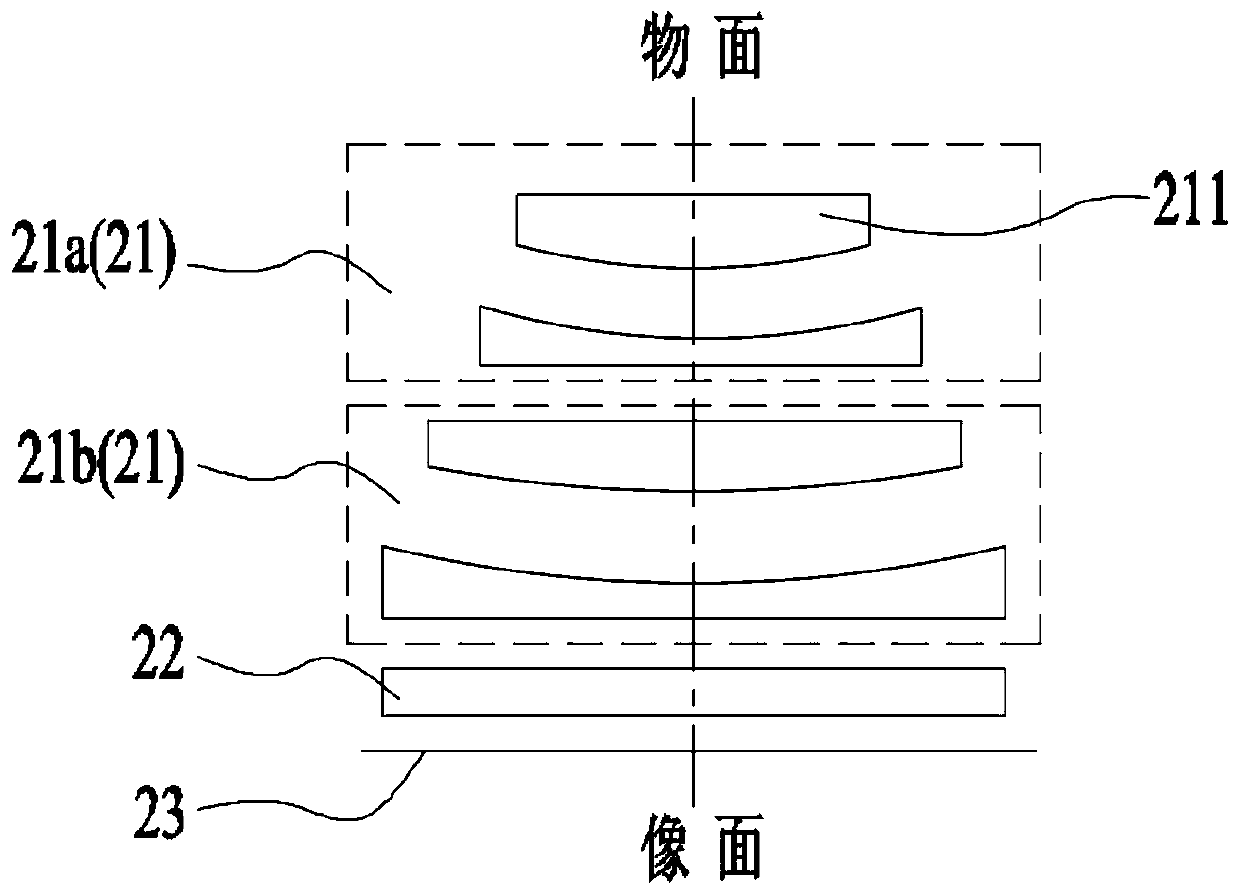
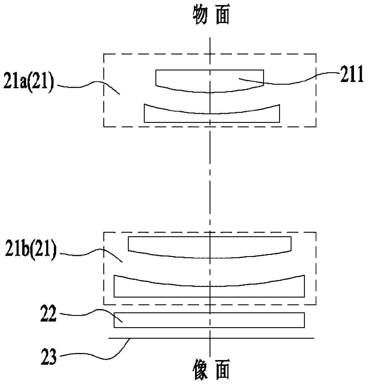
[0040] On the one hand, this application provides a terminal device, please refer to Figure 1 to Figure 4 , the terminal device includes...


PUM


Abstract

The embodiment of the invention provides terminal equipment and a shooting method. The terminal equipment comprises a shell, a fixed-focus camera, a driving mechanism and a control unit, wherein the shell is provided with an accommodating cavity; the fixed-focus camera has an accommodating state and a shooting state; the accommodating state is that the fixed-focus camera is accommodated in the accommodating cavity, and the shooting state is that at least part of the structure of the fixed-focus camera extends out of the accommodating cavity to protrude out of the outer end surface of the shell; the fixed-focus camera comprises at least two lens groups, and at least the lens group close to the object plane can move along the optical axis, so that the fixed-focus camera can be switched between an accommodating state and a shooting state; the driving mechanism is in driving connection with the movable lens group; the control unit is electrically connected with the driving mechanism so asto control the driving mechanism to drive the movable lens group to move along the optical axis. According to the terminal equipment, the EFL of the fixed-focus camera can be increased and the thickness of the Sensor can be increased while the lightening and thinning requirements are met, so that the shooting quality of the fixed-focus camera can be greatly improved.

Description

technical field [0001] The invention relates to the field of mobile devices, in particular to a terminal device and a shooting method. Background technique [0002] In order to improve the shooting quality, two key directions in the mobile phone shooting field are to increase the pixels of the camera and to increase the effective focal length (EFL, effective focal length) of the camera. [0003] However, increasing the pixels means increasing the thickness of the detector (Sensor), and increasing the EFL means increasing the total length (TTL) of the lens (LENS). At present, there are mainly two arrangements of mobile phone cameras in the mobile phone casing, one is arranged in a conventional way, and the other is arranged along the length of the mobile phone (ie, a periscope camera). Mobile phone cameras arranged in a conventional way are usually fixed-focus cameras, and their lenses are arranged along the thickness direction of the mobile phone. Therefore, whether it is t...

Claims


Application Information

Patent Timeline
IPC IPC(8): H04N5/225H04N5/232
CPCH04N23/57H04N23/55H04N23/67H04N23/695
Inventor 杨鑫
Owner GUANGDONG OPPO MOBILE TELECOMM CORP LTD
Learn More